
Power amplifier monitoring method and power amplification circuit

A power amplifier circuit and power amplifier technology, which is applied in the field of power amplifier circuit and power amplifier monitoring, can solve the problems of reducing the performance of the power amplifier, the working status cannot be used, and the working status of the power amplifier cannot be truly detected, so as to achieve accurate monitoring results, Guarantee the effect of working status

Active Publication Date: 2022-03-01
深圳市大族封测科技股份有限公司
View PDF7 Cites 0 Cited by
  • Summary
  • Abstract
  • Description
  • Claims
  • Application Information

AI Technical Summary

Problems solved by technology

[0002] At present, the power amplifier in the power amplifier circuit is often damaged because the power components in the power amplifier are not working in the safe operating area. In the prior art, most of the current output by the power amplifier is monitored through overcurrent protection. When the output current of the amplifier exceeds the threshold value, the overcurrent protection will perform an action to protect the power amplifier circuit, but because the maximum current allowed to work in the safe working area is not constant, it will be affected by other variables of the power component, resulting in the output current of the power amplifier When the threshold value is exceeded but still within the safe operating area, the operating state cannot be exploited, therefore, the operating state of the power amplifier cannot be truly detected, greatly reducing the performance of the power amplifier

Method used


Image

  • Power amplifier monitoring method and power amplification circuit
  • Power amplifier monitoring method and power amplification circuit
  • Power amplifier monitoring method and power amplification circuit

Examples


Embodiment Construction

[0016] The following will clearly and completely describe the technical solutions in the embodiments of the present invention with reference to the accompanying drawings in the embodiments of the present invention. Obviously, the described embodiments are some of the embodiments of the present invention, but not all of them. Based on the embodiments of the present invention, all other embodiments obtained by persons of ordinary skill in the art without creative efforts fall within the protection scope of the present invention.

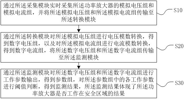
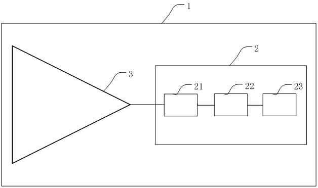
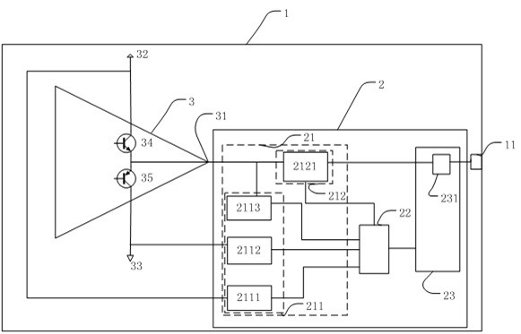
[0017] The present invention provides a power amplifier monitoring method, which is applied to a power amplifier monitoring device 2 in a power amplifier circuit 1, such as figure 2 and image 3 As shown, the power amplifier circuit 1 includes the power amplifier monitoring device 2 and the power amplifier 3, and the power amplifier monitoring device 2 includes an acquisition module 21, a conversion module 22 and a monitoring module 23, and the acquis...


PUM


Abstract

The invention discloses a power amplifier monitoring method and a power amplification circuit, and the method comprises the steps: collecting an analog voltage group and an analog current group of a power amplifier in real time through a collection module, and transmitting the analog voltage group and the analog current group to a conversion module; performing voltage analog-to-digital conversion on the analog voltage group through a conversion module to obtain a digital voltage group, performing current analog-to-digital conversion on the analog current group to obtain a digital current group, and transmitting the digital voltage group and the digital current group to a monitoring module; the monitoring module outputs the working parameters of the digital voltage group and the digital current group to obtain the parameter group and judges the threshold values of the working parameters in the parameter group to obtain the monitoring result, and the monitoring result shows whether the power amplifier works in the safe area or not. The working state of the power amplifier is accurately monitored, and the performance of the power amplifier is fully utilized.

Description

technical field [0001] The invention relates to semiconductor technology, in particular to a power amplifier monitoring method and a power amplifier circuit. Background technique [0002] At present, the power amplifier in the power amplifier circuit is often damaged because the power components in the power amplifier are not working in the safe operating area. In the prior art, most of the current output by the power amplifier is monitored through overcurrent protection. When the output current of the amplifier exceeds the threshold value, the overcurrent protection will perform an action to protect the power amplifier circuit, but because the maximum current allowed to work in the safe working area is not constant, it will be affected by other variables of the power component, resulting in the output current of the power amplifier When the threshold value is exceeded but the working state still in the safe working area cannot be utilized, therefore, the working state of th...

Claims


Application Information

Patent Timeline
IPC IPC(8): H03F1/00G01R31/28H03F3/20
CPCH03F1/00G01R31/2822H03F3/20
Inventor 黎瑾睿姚远卞好洁李峥嵘罗波
Owner 深圳市大族封测科技股份有限公司
Learn More