Electrical discharge machine

A technology for electric discharge processing machines and processed objects, which is applied in the direction of electric processing equipment, metal processing equipment, circuits, etc., can solve the problems of discharge, unspecified time, etc., and achieve the effect of accurate removal amount and accurate calculation

Pending Publication Date: 2022-03-04
SODICK CO LTD
View PDF1 Cites 0 Cited by
  • Summary
  • Abstract
  • Description
  • Claims
  • Application Information

AI Technical Summary

Problems solved by technology

[0008] In addition, there is an unspecified period of time between when a voltage is applied to the machining gap and when a discharge is actually generated.
Therefore, in an electric discharge machining circuit that repeatedly supplies a voltage to the machining gap at a high frequency with short pulse intervals, if no discharge occurs when the switching element is turned on, there may be charges remaining in the machining gap that may cause the switching element to be turned off when the switching element is turned off. When a discharge occurs

Method used


Image

  • Electrical discharge machine
  • Electrical discharge machine
  • Electrical discharge machine

Examples


Embodiment Construction

[0025] Embodiments of the present invention will be described below using the drawings. Various modifications described below can be implemented in any combination.

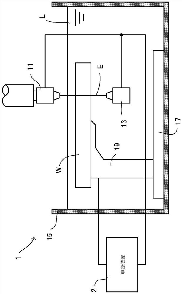
[0026] The electric discharge machine 1 of the present embodiment is a wire electric discharge machine using a wire electrode as the tool electrode E. As shown in FIG. However, the present invention can also be applied to an electrical discharge machining machine using a shaped electrode, a fine-hole electrical discharge machining machine using a rod-shaped electrode or a tubular electrode, and other electrical discharge machining machines.

[0027] like figure 1 As shown, the electric discharge machine 1 of this embodiment includes an upper guide assembly 11 , a lower guide assembly 13 , a machining tank 15 , a table 17 , and a workpiece holder 19 . The table 17 is installed in the processing tank 15 , and the workpiece holder 19 is installed upright on the table 17 . The workpiece W to be processed by electr...


PUM

PropertyMeasurementUnit
electrical resistivityaaaaaaaaaa

Abstract

An electric discharge machine includes a DC power source, a main switching element, a polarity switching circuit, a pulse generation device, a detection device, and a discharge control device. The DC power supply supplies current to the machining gap. The pulse generation device switches the main switching element and either the positive polarity switching element or the reverse polarity switching element of the polarity switching circuit at a predetermined switching frequency. The detection device detects the interelectrode voltage of the machining gap. The discharge control device includes: a storage device that stores, for each operation mode, a coefficient indicating a removal amount per unit discharge number; and a calculation device that calculates the number of discharges from the inter-electrode voltage, and estimates the removal amount from the number of discharges and the coefficient corresponding to the operation mode.

Description

technical field [0001] The present invention relates to an electrical discharge machine. Background technique [0002] In an electrical discharge machine, a workpiece is arranged to face a tool electrode with a predetermined machining gap therebetween. In other words, the workpiece and the tool electrode form a predetermined machining gap. The electric discharge machine applies a machining voltage to the machining gap to generate discharge, and at the same time makes the tool electrode and the workpiece move relatively, and the workpiece is machined into the desired shape through the discharge energy. Hereinafter, the number of discharges generated in the machining gap is referred to as the number of discharges, and the amount removed from the workpiece by the discharges is referred to as the removal amount. [0003] More than one switching element is arranged in series between the DC power supply and the processing gap. By repeatedly turning on / off the switching element ...

Claims


Application Information

Patent Timeline
Patent Type & Authority Applications(China)
IPC IPC(8): B23H1/00B23H1/02B23H11/00
CPCB23H1/00B23H1/02B23H11/00G05F1/46B23H1/022B23H7/20B23H7/02
Inventor 山田邦治远藤庆辉塙智仁
Owner SODICK CO LTD
Why Eureka
Try Eureka