
Automatic separating device and separating method for tray

An automatic separation and suction cup technology, applied in transportation and packaging, object stacking, object destacking, etc., can solve the problems of tray damage, poor separation effect, and low overall comprehensive efficiency, and achieve fast and accurate grasping , Avoid potential safety hazards and reduce labor costs

Pending Publication Date: 2022-03-04
苏州威邦自动化机械有限公司
View PDF0 Cites 1 Cited by
  • Summary
  • Abstract
  • Description
  • Claims
  • Application Information

AI Technical Summary

Problems solved by technology

Most of the trays are stacked together when they are in use and after use. It is necessary to manually separate the product from the tray or the two trays from the tray. The overall overall efficiency of the separation method is low and the separation effect is poor; It is easy to be injured, and at the same time, it may cause damage to the tray when separating the tray
In addition, under normal circumstances, after the tray is artificially separated, the accumulation of the tray is uneven, which affects the normal use of the next process

Method used


Image

  • Automatic separating device and separating method for tray
  • Automatic separating device and separating method for tray
  • Automatic separating device and separating method for tray

Examples


Embodiment Construction

[0052]For the purposes of the present invention, the advantages and features of the present invention will be illustrated and explained by the following preferred embodiments. These embodiments are merely a typical example of the present invention, and any technical solution formed by an equivalent alternative or equivalent transformation is taken within the scope of the invention.

[0053] In the description of the program, it should be noted that the term "center", "upper", "lower", "left", "right", "front", "post", "vertical", "horizontal", " The orientation or position of the inside "," outside ", etc. is based on the orientation or positional relationship shown in the drawings, is merely description and simplified description, rather than indicating or implying that the device or component must have a specific direction. It is constructed to be constructed and operated in a specific orientation, and thus is not to be understood to limit the invention. Moreover, the term "firs...


PUM


Abstract

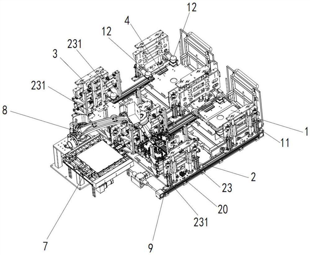
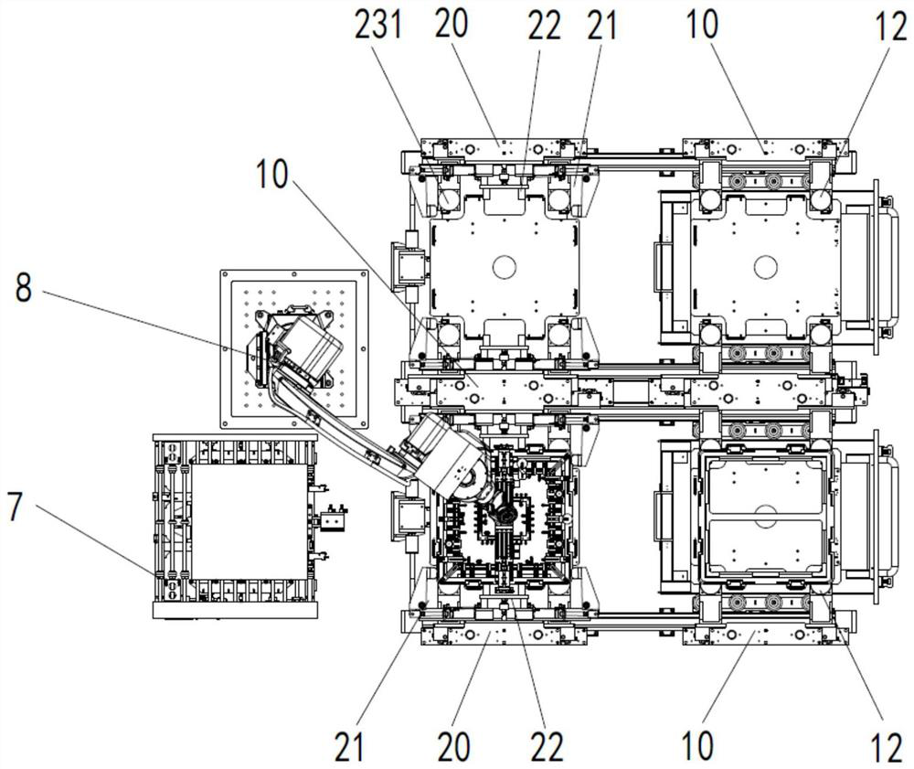
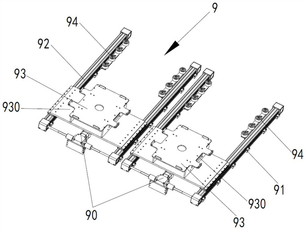
The invention discloses an automatic separating device and method for trays. The automatic separating device comprises a first guide rail and a second guide rail. A supporting seat; a supporting piece is arranged on the inner side of the first air cylinder; the two positioning mechanisms are symmetrically arranged; the floating mechanism at least comprises a material carrying seat; each positioning mechanism comprises an X-axis clamping plate and a Y-axis clamping plate; the clamping mechanism and the clamping mechanism are respectively driven by a positioning cylinder and a positioning motor to clamp or loosen the tray; the material distributing assembly comprises a material carrying seat and a positioning mechanism; the discharging assembly comprises an air cylinder mounting base, a first air cylinder and a supporting piece. The first suction cup and the second suction cup are arranged on the base; the conveying line is located on one side of the manipulator. The automatic feeding device has the beneficial effects that the mechanical arm is adopted to drive the first suction cup and the second suction cup on the mechanical arm to suck the material disc and the product correspondingly, the material disc is placed on the material distributing assembly, the product is placed on the conveying line, separation operation of the material disc and the product is achieved, manual intervention is not needed, and the breakage rate of the material disc and the labor cost are reduced.

Description

Technical field [0001] The present invention belongs to the field of mechanical manufacturing, and more particularly to an automatic separation device and a separation method of TRAY disc. Background technique [0002] TRAY disc, also known as a tray, is used to hold a vessel for processing parts, and is widely used in all walks of life. When the TRAY disk is used and most of them are stacked, it is necessary to manually separate the product and the material plate or two discs and materials, and the overall comprehensive efficiency of the person separation is low, the separation effect is poor; and the staff is also comparable It is easy to be injured, and in the separation of the TRAY disk, it is also possible to cause TRAY discs. In addition, after normal circumstances, the person is separated by the TRAY disc, the stacked range of the TRAY disc is uneven, affecting the normal use of the lower process. [0003] To solve the above problems, it is an important technical issue to ...

Claims


Application Information

Patent Timeline
Patent Type & Authority Applications(China)
IPC IPC(8): B65G47/91B65G61/00B65G47/04
CPCB65G47/914B65G61/00B65G47/04B65G2201/0258
Inventor 徐齐孝李晨
Owner 苏州威邦自动化机械有限公司
Learn More