A liquid flow control valve

A technology for liquid flow and valve control. It is used in lift valves, valve devices, valve details, etc. It can solve problems such as low sensitivity, achieve high precision, reduce vibration and noise, and achieve large adjustment ranges.

Active Publication Date: 2022-08-09
SHANDONG UNIV
View PDF7 Cites 0 Cited by
  • Summary
  • Abstract
  • Description
  • Claims
  • Application Information

AI Technical Summary

Problems solved by technology

[0004] The purpose of the present invention is to overcome the deficiencies of the prior art and provide a liquid flow control valve, which improves the problem of low sensitivity of the control valve in the case of small opening or large opening, improves control accuracy, saves energy, and provides The liquid transmission system away from the power grid provides energy, and it is convenient to install sensors to realize real-time monitoring of the valve and reduce the cavitation phenomenon inside the valve

Method used


Image

  • A liquid flow control valve
  • A liquid flow control valve
  • A liquid flow control valve

Examples


Embodiment 1

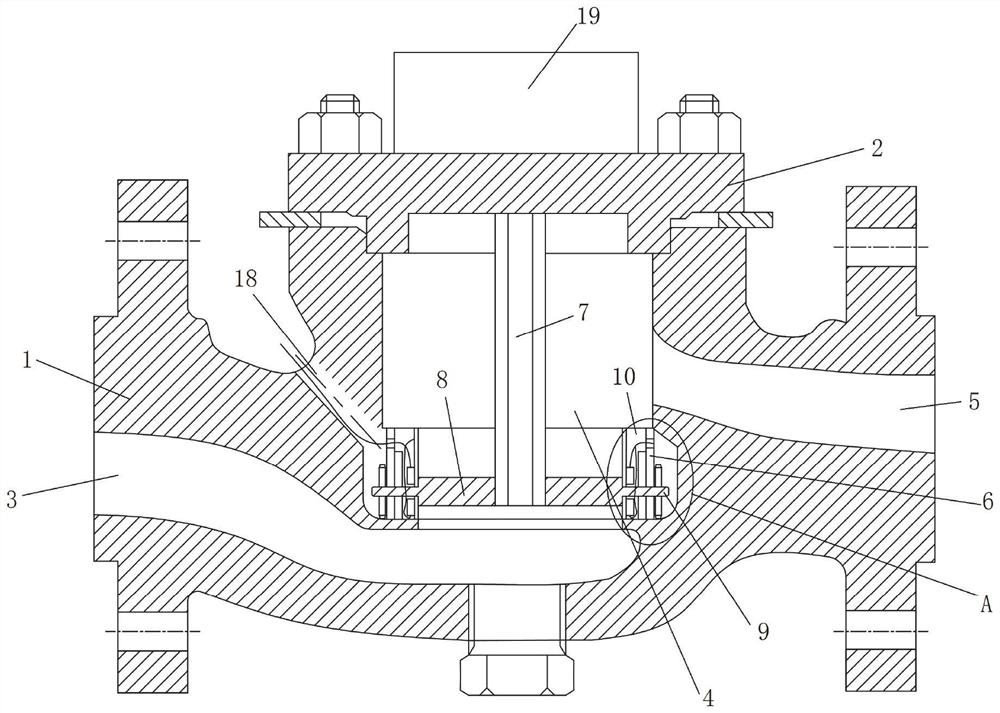
[0040] This embodiment provides a liquid flow control valve, such as Figure 1-Figure 2 As shown in the figure, it includes a valve body 1. The valve body 1 adopts a shell structure, the top of which is fixed with a valve cover 2 by bolts, and the two ends of the valve body 1 are provided with flange structures for connecting with pipelines. A flow channel is provided as a channel for liquid circulation. In this embodiment, the flow channel is composed of a first flow channel part 3, a second flow channel part 4 and a third flow channel part 5 arranged in sequence. The first flow channel The part 3 and the third flow channel part 5 are arranged horizontally, and the second flow channel part 4 is arranged vertically with the first flow channel part 3 and the third flow channel part 5 . The liquid can enter the flow channel from the first flow channel part 3 , pass through the second flow channel part 4 and then flow out from the third flow channel part 5 .

[0041] The second ...


PUM


Abstract

The invention relates to a liquid flow control valve, which comprises a valve body, a flow channel is arranged in the valve body, a valve seat is arranged in the flow channel, the valve body is fixedly connected with a valve stem, the bottom end of the valve stem is located inside the valve seat, and the bottom end of the valve stem is located in the valve seat. There are a plurality of blades distributed along the circumference. The blades are rotatably connected with the valve stem and the valve seat through the rotating shaft. One end of the blade is attached to the valve stem and the other end is attached to the valve seat. The rotating shaft extends to the outside of the valve seat and is connected with the drive mechanism. The two sides of the blade along the circumferential direction of the blade are wave-shaped surfaces, and the two sides of the blade along the circumferential direction of the blade are provided with a plurality of protrusions and grooves, and the protrusions and grooves of adjacent blades can cooperate with each other. The control valve of the invention has high control sensitivity, wide adjustment range and long service life.

Description

technical field [0001] The invention relates to the technical field of fluid flow control equipment, in particular to a liquid flow control valve. Background technique [0002] The statements herein merely provide background related to the present invention and do not necessarily constitute prior art. [0003] A liquid flow control valve, formerly known as a regulating valve, is a mechanism used to regulate flow. In terms of the control system as a whole, the quality of a control system must be realized by the control valve, so the quality of the control valve becomes very important. For the valves that exist today, first of all, because the control valve adopts the throttling principle, the control valve will be accompanied by a certain degree of pressure drop in the process of adjusting the flow. In today's increasingly short supply of energy, these unused pressure Second, high-pressure control valves are usually used in remote fluid transmission systems far away from th...

Claims


Application Information

Patent Timeline
Patent Type & Authority Patents(China)
IPC IPC(8): F16K1/36F16K1/42F16K27/02F16K31/04F16K37/00
CPCF16K1/36F16K1/42F16K27/02F16K31/04F16K37/0025Y02E10/20
Inventor 谢玉东鞠金勇王勇
Owner SHANDONG UNIV
Why Eureka
Try Eureka