Motor cooling mechanism

A technology for motor cooling and motor end caps, applied in cooling/ventilation devices, electrical components, electromechanical devices, etc., can solve the problems of fixed inlet and outlet positions, complex sealing structure, complex processing, etc., and achieve uniform axial temperature and cooling effect. Good, reliable sealing effect

Pending Publication Date: 2022-03-04
CHINA ELECTRONIC TECH GRP CORP NO 18 RES INST
View PDF4 Cites 0 Cited by
  • Summary
  • Abstract
  • Description
  • Claims
  • Application Information

AI Technical Summary

Problems solved by technology

[0005] The helical liquid-cooled motor includes a single helical flow channel and a double helical flow channel. Its disadvantages are: jacket design, complex sealing structure, fixed inlet and outlet positions, and difficulty in shell wall outlet; the disadvantages of the foldback liquid-cooled motor are: pressure loss Larger, complex processing

Method used


Image

  • Motor cooling mechanism
  • Motor cooling mechanism
  • Motor cooling mechanism

Examples


Embodiment Construction

[0026] In order to make the object, technical solution and advantages of the present invention clearer, the present invention will be further described in detail below in combination with specific embodiments and with reference to the accompanying drawings. It should be understood that these descriptions are exemplary only, and are not intended to limit the scope of the present invention. Also, in the following description, descriptions of well-known structures and techniques are omitted to avoid unnecessarily obscuring the concept of the present invention.

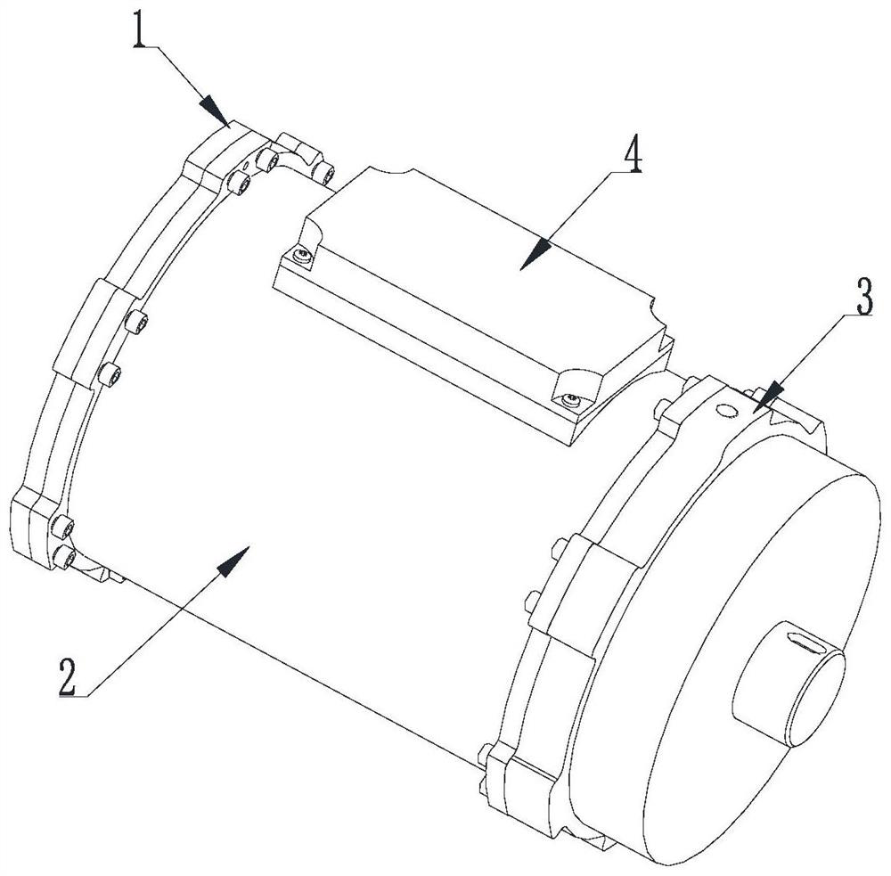
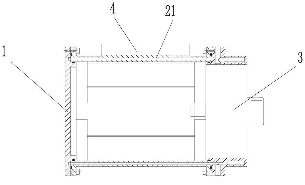
[0027] Such as Figure 1-6 , in the embodiment of the present application, the present invention provides a motor cooling mechanism, including: a motor end cover 1, a housing 2, a reduction box end cover 3 and an electric controller 4, wherein the motor end cover 1 is arranged on The first end of the housing 2, the reduction box end cover 3 is arranged on the second end of the housing 2, the electric controller 4 is arra...


PUM


Abstract

A motor cooling mechanism comprises a motor end cover, a shell, a reduction gearbox end cover and an electric controller, the motor end cover is arranged at the first end of the shell, the reduction gearbox end cover is arranged at the second end of the shell, the electric controller is arranged on the shell, and the electric controller is arranged on the shell. A liquid path pipeline is formed among the motor end cover, the shell and the reduction gearbox end cover, the electric controller is arranged on the outer surface of the shell, and cooling liquid moves in the liquid path pipeline according to a preset direction. According to the motor cooling mechanism provided by the invention, the reduction gearbox, the driving motor and the electric controller can be cooled at the same time, and the cooling effect is good; the axial turn-back type channel in the shell ensures that the axial temperature of the cooling liquid is uniform, the motor end cover, the shell and the reduction gearbox are sealed through the sealing rings, the structure is simple, and sealing is reliable.

Description

technical field [0001] The invention belongs to the technical field of motors, and in particular relates to a motor cooling mechanism. Background technique [0002] Motors are widely used in industry, transportation, equipment and other fields. With the improvement of energy saving requirements, motors are developing in the direction of light weight and high efficiency. The design of the motor generally integrates the drive motor, gearbox, and electric controller. However, during the operation of the motor, the winding current of the drive motor, the friction of the gear train of the gearbox, and the power devices of the electric controller will all generate heat, and the heat accumulation will cause the temperature to rise. , so that the winding resistance increases, the insulation and lubrication properties deteriorate, and the temperature of the power device increases, resulting in a decrease in motor efficiency and even device damage. [0003] At present, motor cooling ...

Claims


Application Information

Patent Timeline
IPC IPC(8): H02K5/20H02K9/19H02K5/04H02K9/193H02K7/10H02K11/30
CPCH02K5/203H02K9/19H02K5/04H02K9/193H02K7/10H02K11/30
Inventor 成海超郝维敏高新龙林沛
Owner CHINA ELECTRONIC TECH GRP CORP NO 18 RES INST
Why Eureka
Try Eureka