Remote time-frequency equipment testing method

A device testing, long-distance technology, applied in the direction of time division multiplexing system, electrical components, multiplexing communication, etc., can solve the test that cannot satisfy the relative frequency accuracy, frequency stability and synchronization accuracy of long-distance distribution , Electrical signal transmission is easily affected by electromagnetic radiation, and it is difficult to meet the test distance requirements, etc., to achieve the effect of long-distance frequency accuracy, low cost, and long-distance time-frequency signal measurement

Pending Publication Date: 2022-03-04
NO 54 INST OF CHINA ELECTRONICS SCI & TECH GRP
View PDF0 Cites 0 Cited by
  • Summary
  • Abstract
  • Description
  • Claims
  • Application Information

AI Technical Summary

Problems solved by technology

The traditional test method uses cables to transmit standard time-frequency signals with time-frequency testing instruments, which cannot meet the test of relative frequency accuracy, frequency stability and synchronization accuracy between long-distance distributed time-frequency devices, and has the following disadvantages:
[0003] 1) The transmission distance of electrical signals is relatively short (usually within 100 meters), which makes it difficult to meet the test distance requirements;
[0004] 2) The electrical signal is transmitted in one direction, the cable delay is greatly affected by factors such as ambient temperature and cable bending, and the test accuracy is low;
[0005] 3) Electrical signal transmission is easily affected by electromagnetic radiation, which affects the stability of the reference signal

Method used


Image

  • Remote time-frequency equipment testing method
  • Remote time-frequency equipment testing method
  • Remote time-frequency equipment testing method

Examples


Embodiment Construction

[0038] In order to make the purpose, technical solution and advantages of the present invention clearer, the technical solution of the present application will be clearly and completely described below in conjunction with the specific embodiments of the application and the corresponding drawings. Apparently, the described embodiments are only some of the embodiments of this application, not all of them. Based on the embodiments in this application, all other embodiments obtained by persons of ordinary skill in the art without making creative efforts belong to the scope of protection of this application.

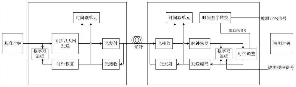
[0039] A long-distance time-frequency signal testing method is used for long-distance time-frequency testing. Such as figure 1 As shown, the implementation of this method requires two devices, the master end and the slave end. The master end device is connected to the time-frequency reference signal, and the slave end device is connected to the measured time-frequency signal...


PUM


Abstract

The invention discloses a long-distance time frequency equipment testing method, and belongs to the field of time frequency testing. According to the invention, the synchronous Ethernet technology is adopted to realize frequency synchronization of the master end and the slave end; coarse synchronization is realized by using an IEEE1588 technology, and a phase difference value of receiving and transmitting clocks of a master end and a slave end is tested by using a digital double-mixing technology and is used as a precise compensation value to improve the synchronization precision of the master end and the slave end; a phase difference value between a measured frequency signal and a far-end recovery frequency signal is realized by using a digital double-frequency mixing technology, and the frequency accuracy and the frequency stability of the measured signal are processed and calculated; a time-to-digital conversion technology is used to realize a time interval between a measured time signal and a far-end recovery pulse signal, and the synchronization precision of the measured signal is processed and calculated.

Description

technical field [0001] The invention relates to the field of time-frequency testing, in particular to a long-distance time-frequency equipment testing method, which can be used for testing the frequency accuracy, stability and synchronization precision parameters of time-frequency signals in a distributed time-frequency system. Background technique [0002] At present, the application development of the time-frequency system is reflected in the characteristics of centralized timekeeping-distributed applications. The system architecture is mostly equipped with hydrogen atomic clocks and cesium atomic clocks as the main time source in the time-frequency center, and traces the source of system time through satellite two-way time comparison, satellite common-view time comparison, satellite one-way time service, etc., and adopts wireless and wired time The means of synchronous delivery distributes the time-frequency signal to each time-consuming node. These time nodes are usuall...

Claims


Application Information

Patent Timeline
IPC IPC(8): H04J3/06
CPCH04J3/0644H04J3/0661
Inventor 杨乐辛鹏飞任亚杰王铮刘铁强贾杰峰霍海强赵岩
Owner NO 54 INST OF CHINA ELECTRONICS SCI & TECH GRP
Why Eureka
Try Eureka