Powder spraying robot for workpiece surface treatment

A workpiece surface and robot technology, applied in the field of robots, can solve the problems of affecting processing efficiency, affecting processing efficiency, and lack of a reference point, etc., to achieve precise powder spraying effect, improve aesthetics, and reduce the effect of moving inconvenience

Pending Publication Date: 2022-03-08
SUSONG ANBAO BUSINESS MACHINE
View PDF10 Cites 0 Cited by
  • Summary
  • Abstract
  • Description
  • Claims
  • Application Information

AI Technical Summary

Problems solved by technology

[0003] At present, most of the powder spraying robots for surface treatment of workpieces on the market have the following deficiencies: 1. When the robot sprays powder on the workpiece, it will move the robot to the place where the workpiece is clamped or the clamping area will be moved to the robot. , the above two methods are extremely cumbersome, not only inconvenient to move, but also affect the processing efficiency in the later stage; 2. There is no alignment base point when spraying powder, it is difficult to grasp the accuracy of powder spraying, and it is easy to cause workpiece needs due to powder spraying errors The phenomenon of rework; 3. Before the workpiece needs to be processed, it is necessary to manually place the workpiece on the workbench or the holder to facilitate the subsequent powder spraying process, but manual operation wastes a lot of time and makes manual labor, which affects the processing efficiency; therefore We urgently need a powder spraying robot for workpiece surface treatment

Method used


Image

  • Powder spraying robot for workpiece surface treatment
  • Powder spraying robot for workpiece surface treatment
  • Powder spraying robot for workpiece surface treatment

Examples


Embodiment

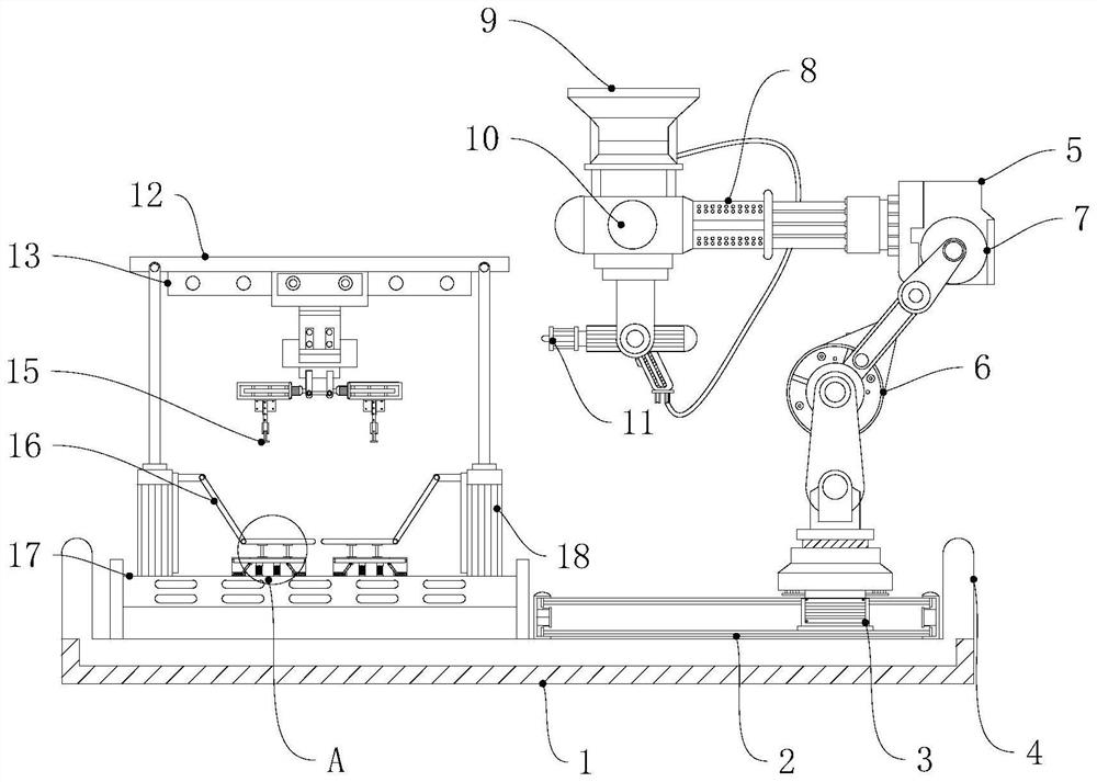
[0027] Example: such as figure 1 As shown, a powder spraying robot for workpiece surface treatment according to the present invention includes a base 1 and a robot body 5. Limiting blocks 4 are arranged on both sides of the top of the base 1, and guide rails 2 and 4 are respectively arranged between the two limiting blocks 4. The clamping mechanism 15, the middle part of the guide rail 2 is provided with a movable block 3, the top of the movable block 3 is fixedly connected with the robot body 5, the robot body 5 includes the first joint 6 and the transmission mechanism for driving the first joint 6, the first joint 6 The bottom of the frame is the machine base, and the top of the first joint 6 is connected to the second joint 7 through the transmission mechanism. The middle part of the second joint 7 is connected to a horizontal arm 8 through the transmission mechanism, and one end of the cross arm 8 is vertically connected through the transmission mechanism. To connect the t...


PUM


Abstract

The powder spraying robot for workpiece surface treatment comprises a base and a robot body, limiting blocks are arranged on the two sides of the top end of the base correspondingly, a guide rail and a clamping mechanism are arranged between the two limiting blocks correspondingly, a movable block is movably arranged in the middle of the guide rail, and the robot body is connected to the top of the movable block; the robot body comprises a first joint and a transmission mechanism for driving the first joint, the top of the first joint is rotationally connected with a second joint through the transmission mechanism, the middle of the second joint is transversely connected with a cross arm through the transmission mechanism, and one end of the cross arm is vertically connected with a third joint through the transmission mechanism; a spray gun body is movably arranged at the bottom of the third joint. The robot and the workpiece clamping area are uniformly arranged on the same bottom plate, and the robot body can transversely move along with the guide rails, so that powder spraying treatment can be conveniently carried out on workpieces in the later period, the working efficiency is improved, and the problems that the workpieces are difficult to clamp and the robot is inconvenient to move are solved.

Description

technical field [0001] The invention relates to the technical field of robots, in particular to a powder spraying robot for workpiece surface treatment. Background technique [0002] Powder spraying refers to a coating process that uses corona discharge to make powder coatings adhere to workpieces. Powder spraying is an essential process in modern high-speed multi-color offset printing processes. Its main function is to prevent the back of printed matter from getting dirty, improve printing quality and efficiency. Powder spraying is made of pure natural plants and refined by modern science. Printing powder spraying is an indispensable tool in offset printing. [0003] At present, most of the powder spraying robots for surface treatment of workpieces on the market have the following deficiencies: 1. When the robot sprays powder on the workpiece, it will move the robot to the place where the workpiece is clamped or the clamping area will be moved to the robot. , the above two...

Claims


Application Information

Patent Timeline
IPC IPC(8): B05B13/04B05B13/02B05B15/00
CPCB05B13/0431B05B13/02B05B15/00
Inventor 姚方兴熊立斌熊立新
Owner SUSONG ANBAO BUSINESS MACHINE
Why Eureka
Try Eureka