Cutting device for batch machining

A cutting device and batch processing technology, applied in the direction of shearing device, feeding device, metal processing equipment, etc., can solve problems such as inconsistent error range, reduced cutting efficiency, and inconvenient use of products, so as to reduce vibration and ensure stability Effect

Pending Publication Date: 2022-03-08
安徽优优时尚科技有限公司
View PDF0 Cites 0 Cited by
  • Summary
  • Abstract
  • Description
  • Claims
  • Application Information

AI Technical Summary

Problems solved by technology

[0004] The purpose of the present invention is to provide a cutting device for batch processing, which aims to improve the existing cutting equipment, which has a simple structure and can only simply cut a single item during use. When the existing cutting equipment is processed, the efficiency is low, and it needs to be processed one by one, which greatly reduces the efficiency of cutting. Moreover, if the traditional cutting equipment is processed in a single piece, it will It may cause the error range in the cutting process of each workpiece to be inconsistent, and it is easy to cause inconvenience to the actual use of the product.

Method used


Image

  • Cutting device for batch machining
  • Cutting device for batch machining
  • Cutting device for batch machining

Examples


Embodiment Construction

[0028] In order to make the purpose, technical solutions and advantages of the embodiments of the present invention clearer, the technical solutions in the embodiments of the present invention will be clearly and completely described below in conjunction with the accompanying drawings in the embodiments of the present invention. Obviously, the described embodiments It is some embodiments of the present invention, but not all of them. Based on the implementation manners in the present invention, all other implementation manners obtained by persons of ordinary skill in the art without creative efforts fall within the protection scope of the present invention. Accordingly, the following detailed description of the embodiments of the invention provided in the accompanying drawings is not intended to limit the scope of the claimed invention, but merely represents selected embodiments of the invention.

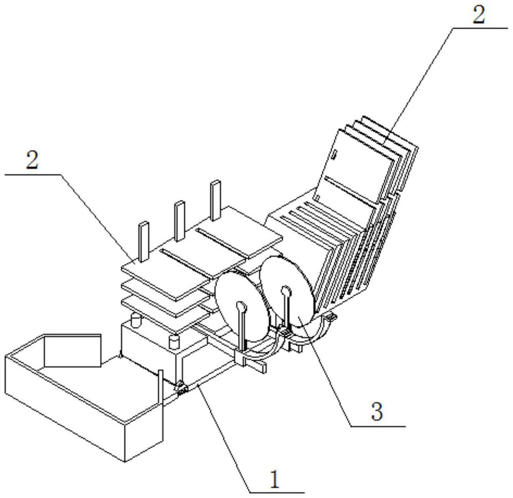
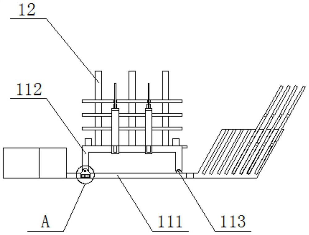
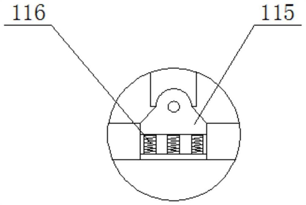
[0029] refer to figure 1 , figure 2 , image 3 , Figure 4 , Figure 5 , ...


PUM


Abstract

The invention discloses a cutting device for batch processing, which comprises an operation frame, laminated plates and a cutting mechanism, a box body comprises a base and vertical plates, the vertical plates are uniformly arranged on the rear end surface of the base, the vertical plates are vertically and fixedly connected with the base, the laminated plates are uniformly arranged in the middles of the vertical plates, and the laminated plates are longitudinally and slidably connected with the vertical plates; the cutting mechanisms are symmetrically arranged at the front end of the base, and the cutting mechanisms are horizontally and slidably connected with the base, so that a user can conveniently and stably place a laminated board in a placement groove of a placement frame without using equipment, and the user can take and use the laminated board at any time; when the cutting device needs to be used, a user can stably pull the cutting mechanism to the head of the guide rod, it is guaranteed that the user can stably place a product needing to be cut on the supporting column, then a laminated plate is taken out of the containing groove and installed on the vertical plate, and the product can be conveniently fixed through the laminated plate and the supporting column.

Description

technical field [0001] The invention relates to the technical field of cutting equipment, in particular to a cutting device for batch processing. Background technique [0002] With the development of the modern mechanical processing industry, the requirements for cutting quality and precision are constantly improving, and the requirements for improving production efficiency, reducing production costs, and highly intelligent automatic cutting functions are also increasing. The development of CNC cutting machines must be To meet the requirements of the development of modern mechanical processing industry, cutting machines are divided into flame cutting machines, plasma cutting machines, laser cutting machines, water cutting, etc. Laser cutting machines have the fastest efficiency, highest cutting precision, and generally small cutting thickness. The cutting speed is also very fast, and the cutting surface has a certain slope. The flame cutting machine is aimed at thicker carbo...

Claims


Application Information

Patent Timeline
IPC IPC(8): B23D19/00B23D33/02B23Q5/28B23Q11/00
CPCB23D19/00B23D33/02B23Q5/28B23Q11/0032
Inventor 施哲峰
Owner 安徽优优时尚科技有限公司
Why Eureka
Try Eureka