Foundation piling device for constructional engineering

Active Publication Date: 2022-03-08
北京优泰信和科技发展有限公司
View PDF7 Cites 3 Cited by
  • Summary
  • Abstract
  • Description
  • Claims
  • Application Information

AI Technical Summary

Problems solved by technology

[0004] In order to overcome the disadvantages of low efficiency, heavy labor, and the need to manually move the pile body into the notch for pile driving, the purpose of the present invention is to provide a high-efficiency, no-need Manual piling, and convenient loading, effectively reducing the amount of labor for construction engineering foundation piling device

Method used


Image

  • Foundation piling device for constructional engineering
  • Foundation piling device for constructional engineering
  • Foundation piling device for constructional engineering

Examples


Embodiment 1

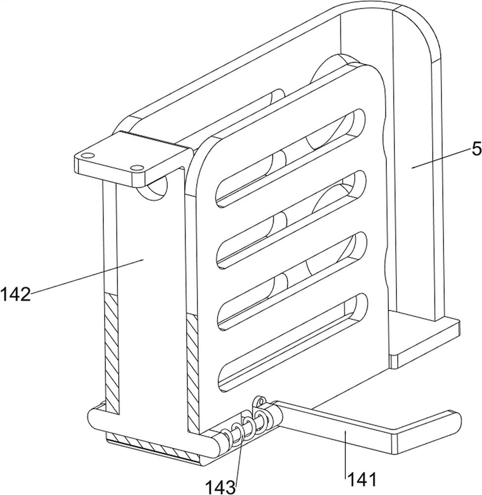
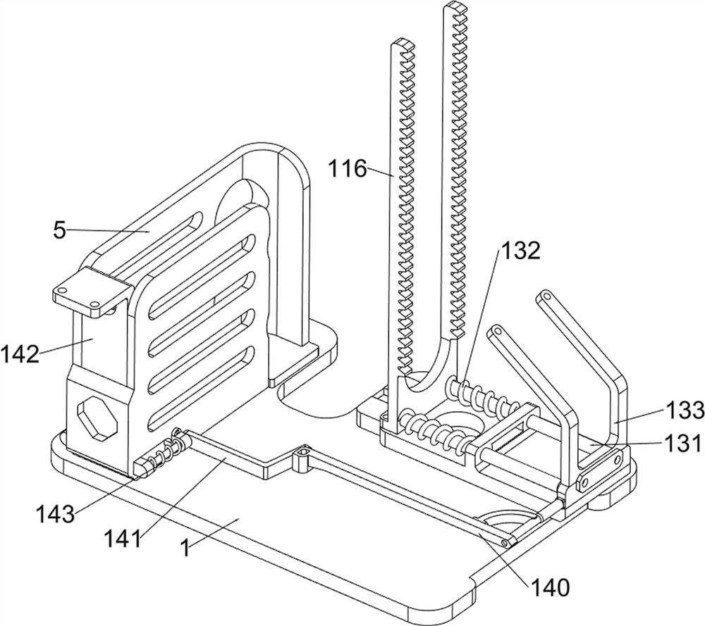
[0033] A construction engineering foundation piling device, such as Figure 1-6 As shown, it includes a base 1, a roller 2, a push handle 3, a first support frame 4, a material storage frame 5, a support column 6, a lifting frame 7, a first spring 8, a pressing block 9, a second spring 10, and a piling mechanism 11 and the blanking mechanism 12, the front and rear sides of the base 1 are equipped with rollers 2 symmetrically rotating left and right, the left side of the base 1 is provided with a push handle 3, and the upper side of the push handle 3 is provided with a rubber sleeve, which can play a non-slip effect. When people pull the push handle 3, it is not easy to slip. The left rear side of the top of the base 1 is connected with the first support frame 4 by means of bolts. A connecting ring for limiting the pile body is welded on the left side of the front part, and a supporting column 6 is welded on the left front side of the top of the base 1, and a lifting frame 7 is...

Embodiment 2

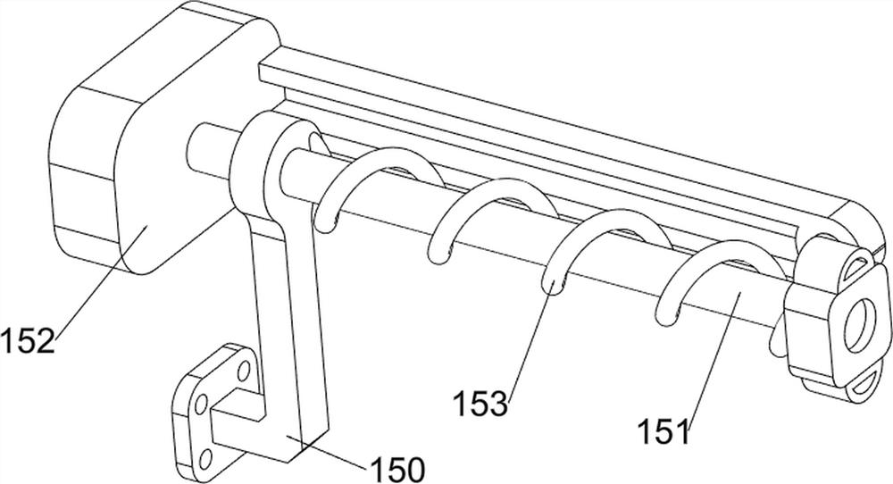
[0038] On the basis of Example 1, such as figure 1 , figure 2 , Figure 7 , Figure 8 , Figure 9 , Figure 10 , Figure 11 and Figure 12 As shown, a reset mechanism 13 is also included. The reset mechanism 13 includes a first push frame 130, a slide bar 131, a fifth spring 132 and a second slide frame 133. The left front side of the top of the base 1 is located at the outside of the support column 6. The front and rear symmetry The sliding type is provided with a slide bar 131, the right ends of the two slide bars 131 are connected with the second rack 116 by bolts, and the second slide frame 133 is connected between the left ends of the two slide bars 131, and the second slide frame 133 slides with the base 1 The second sliding frame 133 is located at the outside of the support column 6, and the left side of the lifting frame 7 is connected with the first pushing frame 130 by means of screw connection. The first pushing frame 130 cooperates with the second sliding fr...


PUM


Abstract

The invention relates to a piling device, in particular to a building engineering foundation piling device. The construction engineering foundation piling device is high in efficiency, free of manual piling, convenient to feed and capable of effectively reducing the labor amount. A construction engineering foundation piling device comprises a base, idler wheels, a push handle, a first supporting frame, a storage frame, a supporting column, a lifting frame and the like, the idler wheels are rotationally arranged on the front side and the rear side in the base in a bilateral symmetry mode, the push handle is arranged on the left side of the base, the first supporting frame is arranged on the left rear side of the top of the base, and the storage frame is arranged on the right side of the top of the base. A supporting column is arranged on the left front side of the top of the base, and a lifting frame is slidably arranged on the upper side of the supporting column. And the motor works to make the pressing block move downwards intermittently to beat the pile body, the pile body is driven into the ground, in this way, the pile body does not need to be driven into the ground manually, and the overall working efficiency is high.

Description

technical field [0001] The invention relates to a piling device, in particular to a construction engineering foundation piling device. Background technique [0002] In the process of building construction, in order to ensure that the ground has sufficient strength to resist pressure, piles are generally driven on the foundation, so that most of the weight of the building is transmitted to a deep position below the ground through the piles, making the foundation of the building stronger. Traditional The traditional piling method is to use drilling to make a notch in the foundation first, and then use a hammer to drive the pile body into the notch, but this manual operation method is difficult to completely drive into the foundation, the piling accuracy is low, and the labor force is strong. And when the pile body is transported, it is mostly transported by a cart. After the notch is opened, it is necessary to manually move the pile body and put it into the notch to carry out ...

Claims


Application Information

Patent Timeline
Patent Type & Authority Applications(China)
IPC IPC(8): E02D7/06E02D7/16
CPCE02D7/06E02D7/16Y02E10/50
Inventor 叶大清
Owner 北京优泰信和科技发展有限公司
Why Eureka
Try Eureka