Syringe piston with improved seal

A seal and piston technology, applied in the field of syringe piston seals, can solve problems such as piston failure and seal failure

Pending Publication Date: 2022-03-08
LINCOLN INDUSTRIES CORP +1
View PDF0 Cites 0 Cited by
  • Summary
  • Abstract
  • Description
  • Claims
  • Application Information

AI Technical Summary

Problems solved by technology

Depending on the seal design, fluid pressure may cause some of the seal material to be squeezed between the head and chamber wall, resulting in seal failure and piston failure

Method used


Image

  • Syringe piston with improved seal
  • Syringe piston with improved seal
  • Syringe piston with improved seal

Examples


Embodiment Construction

[0019] Certain terms are used in the following description for convenience only and not for limitation. The words "inwardly", "inwardly" and "outwardly", "outwardly" refer to directions towards and away from, respectively, the designated centerline or geometric center of the described element, the specific meaning of which will be apparent from the context of the description. Furthermore, as used herein, the words "connected" and "coupled" are each intended to include a direct connection between two components without any other components intervening as well as between components with one or more other components interposed therebetween. indirect connection. The term includes the words specifically mentioned above, derivatives thereof and words of similar import.

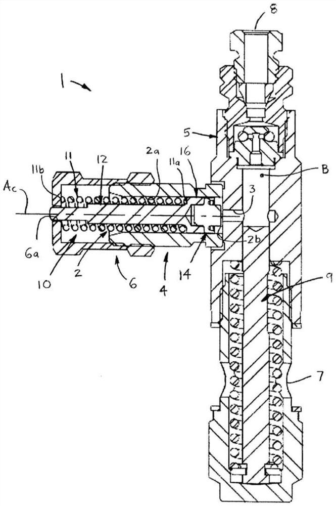
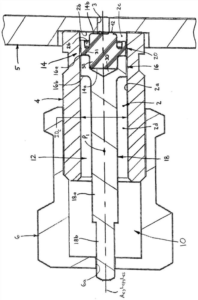
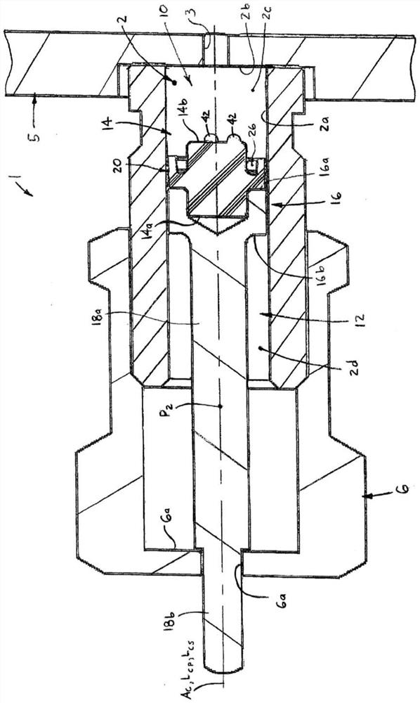
[0020] Referring now in detail to the drawings, wherein like reference numerals are used to denote like elements throughout, Figure 1-12 A dosing piston assembly 10 for a fluid delivery device 1 is shown, prefera...


PUM


Abstract

A piston assembly for a fluid delivery device, preferably a lubricant syringe, having a measurement chamber defined by an inner cylindrical surface and an axial end face, a flow port through the end face, and a central axis extending through the chamber. A piston assembly includes a piston body disposed within the chamber so as to be linearly movable along a central axis. The piston body includes a cylindrical head having first and second axial ends and an outer circumferential surface, and a rod extending axially from the second axial end of the piston head. A seal is coupled with the first axial end of the piston head and has an annular lip sealingly engageable with the chamber interior cylindrical surface and an axial end engageable with the chamber end face.

Description

technical field [0001] The present invention relates to seals and, more particularly, to seals for syringe plungers. Background technique [0002] Lubricant injectors typically include metering chambers to meter the desired amount of lubricant for subsequent injection into specific points to be lubricated, such as bearings, gear surfaces, etc. A piston is positioned within the chamber and moves away from the port as lubricant enters the chamber until a stop point is reached at which point the chamber fills with the desired amount. Thereafter, through the subsequent return stroke of the piston, the lubricant is expelled from the chamber through the port. [0003] A typical lubricant piston includes a head slightly smaller in size than the measurement chamber bore and a stem extending from the rear end of the head which serves to guide the head and provide an external visual indicator. During filling and expulsion of lubricant, the piston head must be sealed to prevent leaka...

Claims


Application Information

Patent Timeline
Patent Type & Authority Applications(China)
IPC IPC(8): F04B53/14F04B13/00F04B53/16F16N13/02
CPCF04B53/14F04B53/143F04B13/00F04B53/16F16N13/02F16J1/008F16N25/02F16N27/00F16J9/12
Inventor B.格林C.霍兰德T.麦克布莱德
Owner LINCOLN INDUSTRIES CORP
Why Eureka
Try Eureka