
Hooking piece, hooking structure and electrical equipment assembly

An electrical equipment and hooking technology, applied in electrical components, electrical equipment shells/cabinets/drawers, mechanical equipment, etc., can solve the problems of large activity space, unstable and unstable installation of electrical equipment, etc., to achieve a wide range of applications. Effect

Pending Publication Date: 2022-03-08
厦门科华数能科技有限公司
View PDF0 Cites 0 Cited by
  • Summary
  • Abstract
  • Description
  • Claims
  • Application Information

AI Technical Summary

Problems solved by technology

But this kind of hook hanger is generally only the sheet metal structure that protrudes from the hook hanger because the hook groove that is provided with on it, after the hook is finished, the activity space in the horizontal direction is large, not stable enough
In addition, when the weight of the electrical equipment is heavy, the hooking groove is easily deformed due to the large tensile force, which will lead to the installation of the electrical equipment not being stable enough, and there may even be a risk of falling

Method used


Image

  • Hooking piece, hooking structure and electrical equipment assembly
  • Hooking piece, hooking structure and electrical equipment assembly
  • Hooking piece, hooking structure and electrical equipment assembly

Examples


Embodiment Construction

[0032] The following will clearly and completely describe the technical solutions in the embodiments of the present invention with reference to the drawings in the embodiments of the present invention. Obviously, the described embodiments are preferred embodiments of the invention and should not be seen as excluding other embodiments. Based on the embodiments of the present invention, all other embodiments obtained by persons of ordinary skill in the art without creative efforts fall within the protection scope of the present invention.

[0033] In the claims, description and above-mentioned drawings of the present invention, unless otherwise clearly defined, the terms "first", "second" or "third" are used to distinguish different objects, not for Describe a specific order.

[0034]In the claims, specification and above-mentioned drawings of the present invention, unless otherwise clearly defined, for orientation words, such as using the terms "center", "transverse", "longitu...


PUM


Abstract

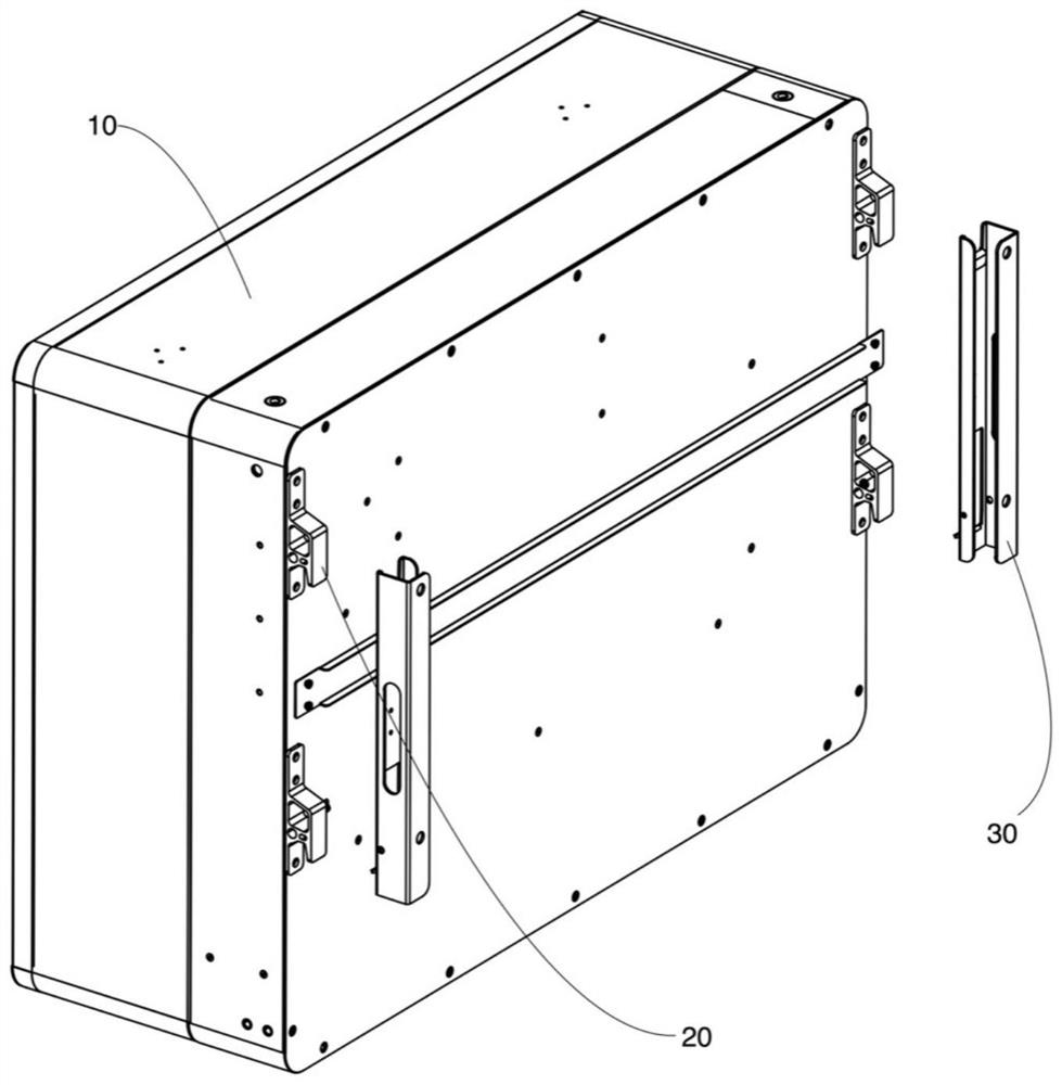
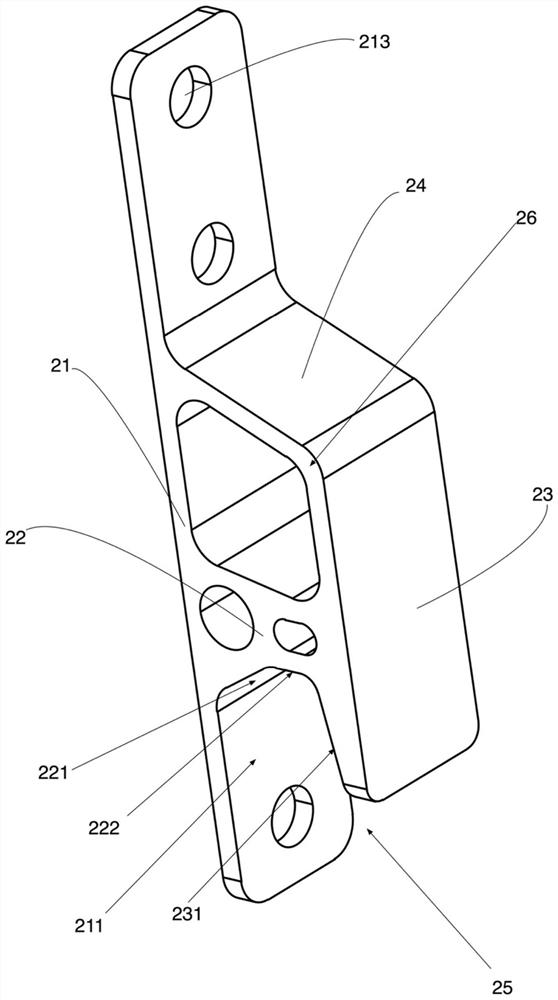
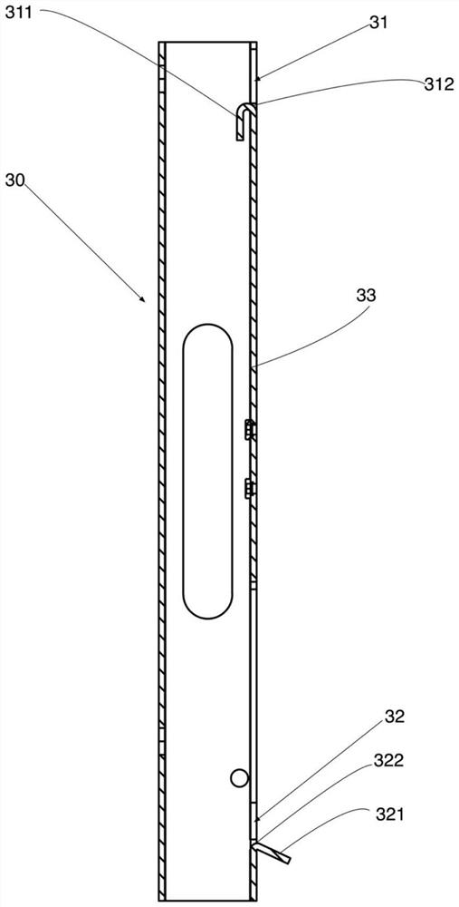
The invention discloses a hooking piece, a hooking structure and an electrical equipment assembly, a hooking groove with a downward opening is defined by a third plate, a first plate and a second plate which are arranged on the hooking piece, a first surface, a second surface, a third surface and a fourth surface which are connected in sequence are formed in the hooking groove, and the first surface, the third surface and the fourth surface are located on the first plate, the second plate and the third plate respectively. The second surface is located on the second plate or the first plate; the third surface is perpendicular to the first plate and is suitable for abutting against and matching with the wall surface support, and the second surface is inclined upwards relative to the first surface and is suitable for guiding and matching with the wall surface support; meanwhile, the wall surface bracket is arranged in the hooking structure, and the first extension arm and the second extension arm are arranged on the wall surface bracket, so that the hung wall-mounted equipment can be kept in a vertical state after being hung by the wall-mounted structure, the transverse shearing force borne by the hooking piece is reduced, the deformation of the hooking piece is avoided, and the safety of the hooking piece is improved. The hooking piece can be suitable for hanging heavy equipment, can limit the moving space of the wall hanging equipment in the horizontal direction after hooking is completed, has a wide application range, and can effectively improve the structural stability of the hooking piece during hooking.

Description

technical field [0001] The invention relates to the technical field of hooking structures, in particular to a hooking piece, a hooking structure and an electrical equipment assembly. Background technique [0002] The current electrical equipment, such as inverters, is gradually being miniaturized, and the installation method is generally changed from the grounding type to the wall-mounted type with a smaller footprint. The existing wall hanging structure generally includes a wall bracket fixed on the wall and a hook piece fixed on the electrical equipment. When installing, just hook the hooking groove of the hooking piece directly to the hooking flange of the wall bracket. But this hook hanger is generally only the sheet metal structure that stretches out from the hook hanger because the hook groove that is provided with on it, after the hook is hung, the activity space in horizontal direction is big, not stable enough. In addition, when the weight of the electrical equipm...

Claims


Application Information

Patent Timeline
IPC IPC(8): F16B45/00F16M13/02H05K5/02
CPCF16B45/00F16M13/022H05K5/0204
Inventor 伍毓民刘艺超林镇煌
Owner 厦门科华数能科技有限公司
Learn More