Optical fiber fluid temperature measurement method and system for engine pipeline digital twin model

A fluid temperature measurement and engine technology, which is applied to thermometers, thermometers, measuring devices, etc. with physical/chemical changes, which can solve the influence of the internal space of the pipeline, the inaccurate temperature parameter values, and the inability to truly simulate the temperature parameters of the fluid in the pipeline, etc. problem, to achieve the effect of strong authenticity and small occupation

Pending Publication Date: 2022-03-08
THE SECOND RES INST OF CIVIL AVIATION ADMINISTRATION OF CHINA
View PDF0 Cites 0 Cited by
  • Summary
  • Abstract
  • Description
  • Claims
  • Application Information

AI Technical Summary

Problems solved by technology

The structures of the above schemes will all affect the internal space of the pipeline, affect the flow state of the fluid in the pipeline to a certain extent, and cannot truly simulate the temperature parameters of the fluid in the pipeline under normal flow, and the obtained temperature parameter values ​​are not accurate. It has reference value, and it is impossible to establish a digital twin model that conforms to the authenticity of the corresponding pipeline of the aircraft with the node parameters including these temperature parameters

Method used


Image

  • Optical fiber fluid temperature measurement method and system for engine pipeline digital twin model
  • Optical fiber fluid temperature measurement method and system for engine pipeline digital twin model
  • Optical fiber fluid temperature measurement method and system for engine pipeline digital twin model

Examples


Embodiment 1

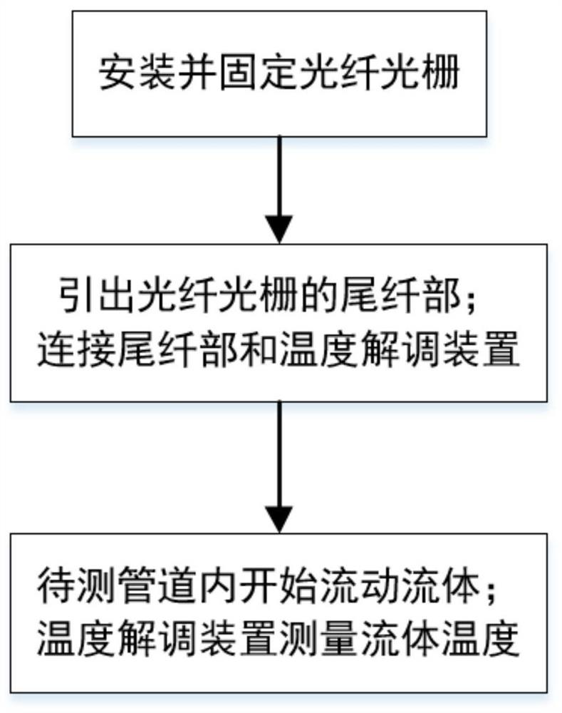
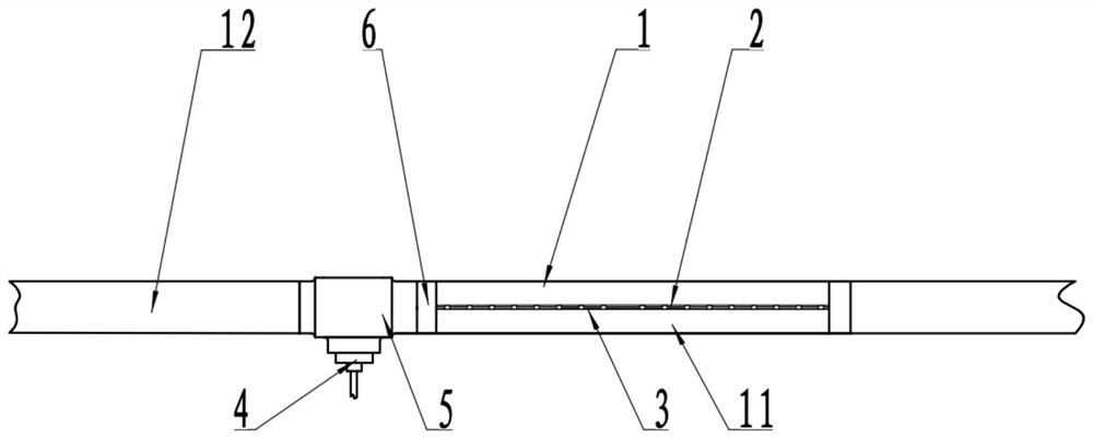
[0046] The embodiment is basically as attached figure 1 , figure 2 Shown: A fiber optic fluid temperature measurement method for a digital twin model of an engine pipeline, including the following steps:

[0047] Step 1: install the fiber grating 2 so that the fiber grating 2 passes through the pipeline 1 to be tested and does not touch the inner pipe wall of the pipeline 1 to be tested; fix the fiber grating 2 .

[0048] When fixing the fiber grating 2, the fiber grating 2 is fixed by using a triangular fixing frame 6, and the triangular fixing frame 6 is arranged at the end and tail of the temperature measuring section 11 of the pipeline 1 to be tested. When installing the fiber grating 2, the position of the fiber grating 2 is also adjusted so that the axis of the fiber grating 2 is parallel to the axis of the pipeline to be tested 1, and the distance between the axis of the fiber grating 2 and the axis of the pipeline to be tested is a preset distance. In this embodimen...

Embodiment 2

[0066] This embodiment provides a fiber optic fluid temperature measurement method for a digital twin model of an engine pipeline, which is the same as the method described in Embodiment 1, so details are not repeated here.

[0067] This embodiment also provides a fiber optic fluid temperature measurement system for the digital twin model of the engine pipeline. On the basis of Embodiment 1, a temperature alarm module and a calibration module are added to the temperature demodulation device. The temperature alarm module Both the calibration module and the calibration module are located in the signal processing device. The temperature alarm module is used to monitor the temperature of each temperature collection point on the fiber grating 2. When the temperature value is abnormal, it will immediately give an alarm in the form of voice notification or SMS notification. Specifically, when the temperature of the fluid in the pipeline exceeds the threshold temperature, an alarm is i...

Embodiment 3

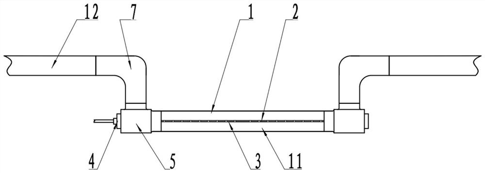
[0070] as attached image 3 As shown, the fiber optic fluid temperature measurement method for the digital twin model of the engine pipeline is based on the first embodiment, and the installation and connection methods of the fiber grating 2 in steps 1 and 2 are changed.

[0071] Step 1: install the fiber grating 2 so that the fiber grating 2 passes through the pipeline 1 to be tested and does not touch the inner pipe wall of the pipeline 1 to be tested; fix the fiber grating 2 .

[0072] When fixing the fiber Bragg grating 2, a three-way connector 5 is used to fix the pipe, and a three-way connector 5 is installed at the end and tail of the temperature measurement section 11. The temperature measuring section 11 of the measuring pipe 1, the non-temperature measuring section 12 and the lead-out part of the pigtail part of the fiber Bragg grating 2. At the same time, when the non-temperature-measuring section 12 of the pipeline 1 to be tested is connected, the non-temperature-...


PUM


Abstract

The invention relates to the technical field of fluid temperature measurement, and discloses an optical fiber fluid temperature measurement method and system for an engine pipeline digital twin model, and the method comprises the following steps: 1, installing a fiber bragg grating, enabling the fiber bragg grating to pass through a to-be-measured pipeline, and not to make contact with the inner pipe wall of the to-be-measured pipeline; adjusting the position of the fiber bragg grating to enable the distance between the axis of the fiber bragg grating and the axis of the to-be-measured pipeline to be a preset distance; fixing the fiber grating; 2, leading out a tail fiber part of the fiber bragg grating; connecting the tail fiber part and the temperature demodulation device; 3, starting to flow fluid in the to-be-detected pipeline; and the temperature demodulation device measures the temperature of fluid in the to-be-measured pipeline through the fiber bragg grating. The fluid temperature in the pipeline can be accurately measured, the structure is simple, the operation is convenient, the applicability is high, the constructed testing environment is close to a real application environment, and the testing authenticity is high.

Description

technical field [0001] The invention relates to the technical field of fluid temperature measurement, in particular to an optical fiber fluid temperature measurement method and system for a digital twin model of an engine pipeline. Background technique [0002] The normal operation of the pipeline system of the aircraft is the guarantee for the normal operation of the overall system of the aircraft. Since the shapes, structures and installation positions of the various parts of the aircraft engine are quite different, as well as the types of oil flowing inside and the working conditions (temperature, pressure, flow, etc.), different pipelines need to be developed separately Pipeline performance tests, such as pipeline fire tests, are not only dangerous, but also costly and require a long verification period. With the rapid development of simulation technology, it has been proposed to establish a digital twin model of the engine's external pipelines and components, and perfo...

Claims


Application Information

Patent Timeline
Patent Type & Authority Applications(China)
IPC IPC(8): G01K11/3206
CPCG01K11/3206
Inventor 陈龙陈元王玉琢马震武斌于新华
Owner THE SECOND RES INST OF CIVIL AVIATION ADMINISTRATION OF CHINA
Why Eureka
Try Eureka