Pulser testing device, pulser testing system and pulser testing method

A technology of testing device and pulser, applied in the direction of testing, measuring device and measurement of machine/structural components, which can solve the problem that it is difficult to determine whether the main valve or the pulse generator occurs. 1. The accuracy of the test results is low and difficult Eliminate problems such as the influence of the main valve, and achieve the effect of avoiding damage and accurate test results

Pending Publication Date: 2022-03-08
航天科工惯性技术有限公司 +2
View PDF0 Cites 0 Cited by
  • Summary
  • Abstract
  • Description
  • Claims
  • Application Information

AI Technical Summary

Problems solved by technology

[0004] Since the existing test methods fail to simulate the pressure environment of the downhole drilling fluid, the test results can only represent the working performance of the pulse generator 1 under normal pressure, and the accuracy of the test results is low; in addition, the single pulse generator 1 It is impossible to test in the field. Even if the pulse generator 1 is combined with the main valve in the field test, it is difficult to rule out the influence of the main valve on the test results. When the test results cannot be passed, it is difficult to determine whether the problem occurs in the main valve or Pulse generator 1

Method used


Image

  • Pulser testing device, pulser testing system and pulser testing method
  • Pulser testing device, pulser testing system and pulser testing method
  • Pulser testing device, pulser testing system and pulser testing method

Examples


Embodiment Construction

[0031] The following will clearly and completely describe the technical solutions in the embodiments of the present invention with reference to the accompanying drawings in the embodiments of the present invention. Obviously, the described embodiments are only some, not all, embodiments of the present invention. Based on the embodiments of the present invention, all other embodiments obtained by persons of ordinary skill in the art without making creative efforts belong to the protection scope of the present invention.

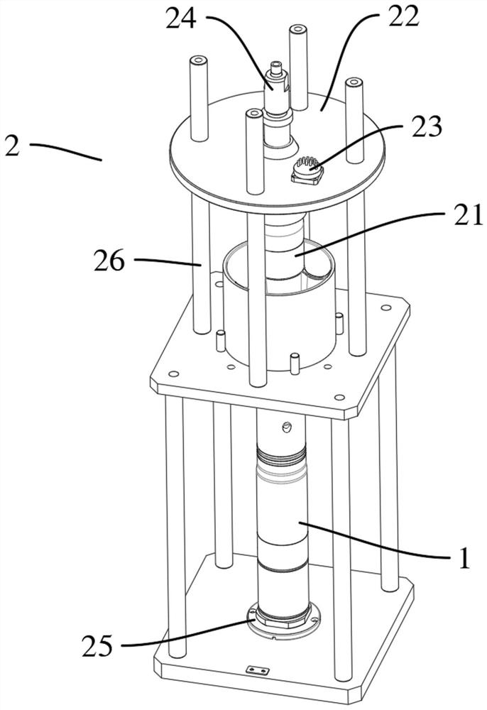
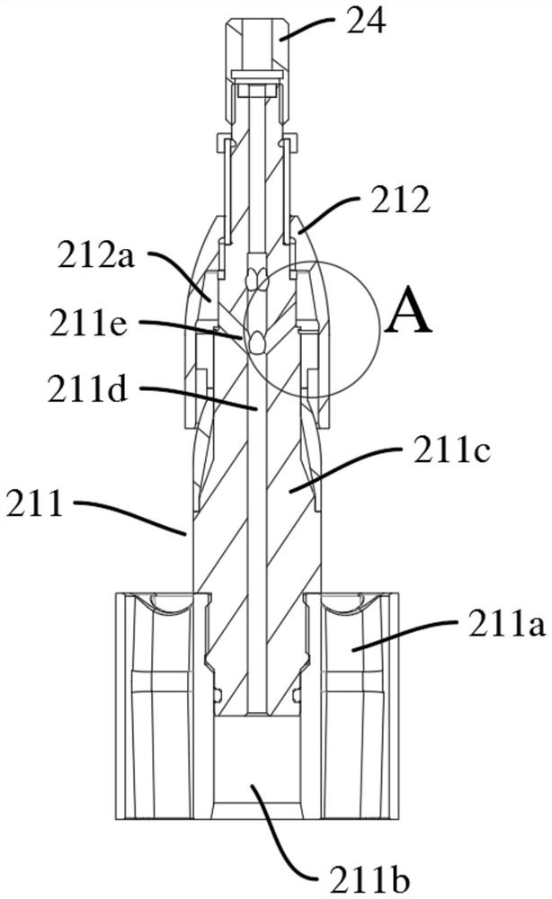
[0032] see Figure 2 to Figure 5 , the embodiment of the present invention provides a test device 2 for a pulser, including: a simulated main valve 21; The pressure feedback part 212 on the connecting part 211; the pressure feedback part is provided with an analog load 22, and an acceleration sensor (not shown in the figure) and an acquisition communication component 23 connected to the acceleration sensor are fixed on the analog load 22, The acquisition comm...


PUM


Abstract

The invention provides a testing device of a pulser. The testing device comprises a simulation main valve; the simulation main valve comprises a connecting part used for being connected with a pulser to be tested and a pressure feedback part which can be installed on the connecting part in an up-and-down moving mode. A simulation load is arranged on the pressure feedback part, an acceleration sensor and an acquisition communication assembly connected with the acceleration sensor are fixed on the simulation load, and the acquisition communication assembly is used for receiving a signal acquired by the acceleration sensor and then outputting the signal to terminal equipment; and a gas source supply assembly is communicated with the simulation main valve and is used for conveying high-pressure gas to the simulation main valve so as to simulate the pressure of underground drilling fluid. The simulation of an underground environment is realized through the simulation load and the gas source supply assembly, and the accuracy of a test result is improved; the high-pressure gas does not cause pollution to the pulser, so that damage to the tested pulser in the testing process is avoided; in addition, through the arrangement of the simulation main valve, the problem that the influence of the main valve on the test result is difficult to eliminate is solved.

Description

technical field [0001] The invention relates to the field of pulser testing, in particular to a pulser testing device, system and pulser testing method. Background technique [0002] In the field of oil exploration and drilling, the use of drilling equipment is very common. The core of drilling equipment is the drill bit, so it is necessary to monitor the drilling status of the drill bit at any time. However, with the deepening of drilling, the drill bit will go deep into the formation, and it is difficult for the staff on the ground to directly observe the situation of the drill bit; at present, the way of communication between the ground and the downhole is generally to use a pulse generator to control the drilling fluid delivery pipeline. The principle is to set up a pulse generator in the mud flow channel. The pulse generator opens / blocks the drilling fluid flow channel according to certain rules, so that the mud flow channel generates regular pulses. The ground staff d...

Claims


Application Information

Patent Timeline
IPC IPC(8): G01M99/00G01R31/00E21B47/18
CPCG01M99/005G01M99/007G01R31/00E21B47/18
Inventor 胡雄焦刚肖占鹏吕伟郑海波刘焕雨张德军梁涛廖冲孙炳章唐雅琴
Owner 航天科工惯性技术有限公司
Why Eureka
Try Eureka