Single-cavity three-mode ceramic waveguide resonator and filter

A waveguide filter and waveguide resonance technology, which is applied to waveguide-type devices, circuits, electrical components, etc., can solve the problem of difficulty in meeting the requirements of small size and high out-of-band suppression characteristics at the same time, so as to improve the out-of-band suppression characteristics and reduce the volume effect

Active Publication Date: 2022-03-08
HUAZHONG UNIV OF SCI & TECH
View PDF5 Cites 1 Cited by
  • Summary
  • Abstract
  • Description
  • Claims
  • Application Information

AI Technical Summary

Problems solved by technology

Therefore, it is difficult for this technology to meet the requirements of small size and high out-of-band suppression characteristics at the same time

Method used


Image

  • Single-cavity three-mode ceramic waveguide resonator and filter
  • Single-cavity three-mode ceramic waveguide resonator and filter
  • Single-cavity three-mode ceramic waveguide resonator and filter

Examples


Embodiment 1

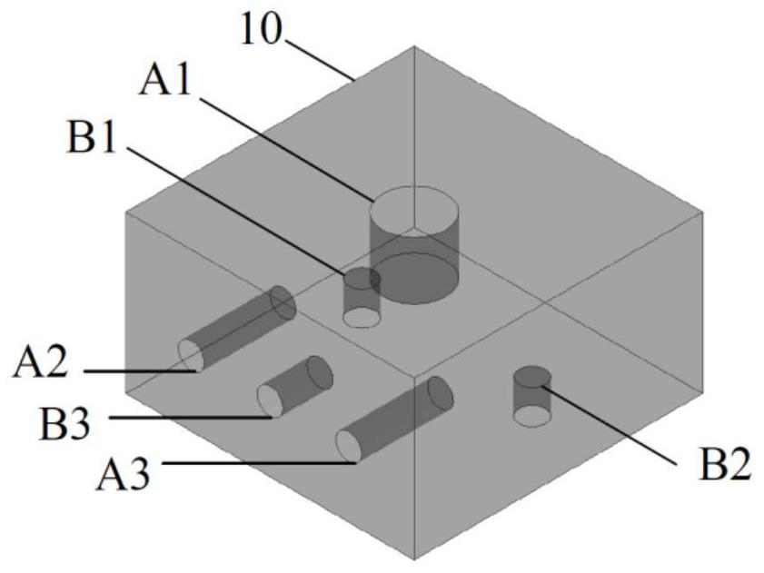
[0050] Such as figure 1 As shown, in one of the embodiments of the present invention, a single-cavity three-mode ceramic waveguide resonator is provided, including a ceramic waveguide resonator body 10 with a metal coating on the surface, three tuning blind holes on the surface of the body, and three Coupling blind vias.

[0051] The three tuning blind holes provided on the surface of the resonator body are tuning blind hole A1, tuning blind hole A2 and tuning blind hole A3, wherein the tuning blind hole A1 is located on the upper surface of the resonator, and the depth of the blind hole is adjustable. Adjust the depth of the tuning blind hole A1 to adjust the resonant frequency of the TE101 mode of the resonator. The tuning blind hole A2 and the tuning blind hole A3 are located on the side of the resonator. In this embodiment, the tuning blind hole A2 and the tuning blind hole A3 are located on the same side (based on figure 1 Look, it is located at the front of the four si...

Embodiment 2

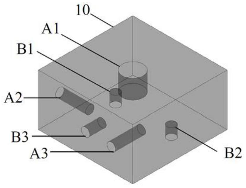
[0056] Such as figure 2 As shown, different from Embodiment 1, in this embodiment, the tuning blind hole A2 and the tuning blind hole A3 are located on adjacent sides (based on the attached figure 2 See, respectively located on the left side and the front side in the side), the coupling blind hole B3 can be located on any one of the four sides, and the depth of the coupling blind hole B3 is less than the tuning blind hole A2 and the tuning blind hole A3 arranged on the side. At this time, the coupling between the two quasi-TEM modes is negative coupling, and the resonator can be regarded as a capacitive CT structure, which will generate a transmission zero at the low frequency end of the passband.

Embodiment 3

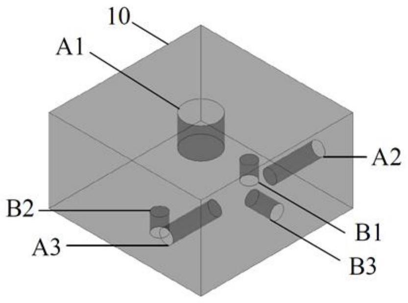
[0058] Such as image 3 As shown, different from Embodiment 1, in this embodiment, the tuning blind hole A2 and the tuning blind hole A3 are located on two opposite sides (based on the attached image 3 Look, they are respectively located at the front and rear of the sides), and the coupling blind hole B3 can be located at any one of the four sides. At this time, the coupling between the two quasi-TEM modes is negative coupling, and the resonator can be regarded as a capacitive CT structure, which will generate a transmission zero at the low frequency end of the passband.


PUM


Abstract

The invention discloses a single-cavity three-mode ceramic waveguide resonator and a filter, and belongs to the technical field of microwave communication. The resonator comprises a ceramic waveguide resonator body, three tuning blind holes and three coupling blind holes, the three tuning blind holes and the three coupling blind holes are located in the surface of the body, the tuning blind hole A1 and the coupling blind holes B1 and B2 are oppositely formed in the upper surface and the lower surface of the body, and the tuning blind holes A2 and A3 and the coupling blind holes B3 are formed in the four side faces. The depth of the coupling blind hole B3 is smaller than the depths of the tuning blind holes A2 and A3; the tuning blind hole A1 is used for adjusting the resonant frequency of a TE101 mode of the resonator, and the tuning blind holes A2 and A3 are respectively used for adjusting the resonant frequencies of two quasi TEM modes; the coupling blind hole B1 and the coupling blind hole B2 are respectively used for adjusting the coupling bandwidth between the TE101 mode of the resonator and the two quasi TEM modes, and the coupling blind hole B3 is used for adjusting the coupling bandwidth between the two quasi TEM modes. The size of the ceramic waveguide filter is reduced, and the out-of-band rejection characteristic of the filter is improved.

Description

technical field [0001] The invention belongs to the technical field of microwave communication, and more specifically relates to a single-cavity three-mode ceramic waveguide resonator and filter. Background technique [0002] The rapid development of contemporary communication technology and limited spectrum resources have put forward higher requirements on the size and performance of base station filters. Ceramic waveguide filters have become the mainstream choice for current 5G base station filters due to their unique advantages such as small size and high performance. In order to further reduce the size of the filter, the ceramic waveguide filter usually needs to use a single-cavity multimode resonator to complete the design; on the other hand, in order to effectively improve the out-of-band suppression characteristics of the filter, the designer needs to construct a CT or a capacitive CQ coupled structures to generate transmission zeros. [0003] The design of medium a...

Claims


Application Information

Patent Timeline
Patent Type & Authority Applications(China)
IPC IPC(8): H01P1/208
CPCH01P1/2082
Inventor 梁飞蒙顺良尹宇豪张榕吕文中王晓川
Owner HUAZHONG UNIV OF SCI & TECH
Why Eureka
Try Eureka