Tubular workpiece synchronous rotating and clamping mechanism and welding system based on visual inspection

A clamping mechanism and synchronous rotation technology, applied in welding equipment, auxiliary welding equipment, welding/cutting auxiliary equipment, etc., to achieve the effect of improving production efficiency, reducing rework costs, and ensuring welding quality

Active Publication Date: 2022-03-11
北京东方国信科技股份有限公司
View PDF10 Cites 6 Cited by
  • Summary
  • Abstract
  • Description
  • Claims
  • Application Information

AI Technical Summary

Problems solved by technology

[0006] The present invention provides a synchronous rotating clamping mechanism for tubular workpieces and a welding system based on visual inspection, which are used to solve or improve at least one technical problem existing in the prior art, so as to better clamp longer tubular workpieces Hold to ensure the horizontal posture of the tubular workpiece when performing girth welding

Method used


Image

  • Tubular workpiece synchronous rotating and clamping mechanism and welding system based on visual inspection
  • Tubular workpiece synchronous rotating and clamping mechanism and welding system based on visual inspection
  • Tubular workpiece synchronous rotating and clamping mechanism and welding system based on visual inspection

Examples


Embodiment Construction

[0033] In order to make the purpose, technical solutions and advantages of the present invention clearer, the technical solutions in the present invention will be clearly and completely described below in conjunction with the accompanying drawings in the present invention. Obviously, the described embodiments are part of the embodiments of the present invention , but not all examples. Based on the embodiments of the present invention, all other embodiments obtained by persons of ordinary skill in the art without creative efforts fall within the protection scope of the present invention.

[0034] Combine below Figure 1-Figure 11 A synchronous rotating clamping mechanism for tubular workpieces and a welding system based on visual inspection of the present invention are described.

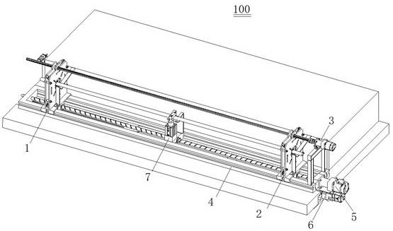
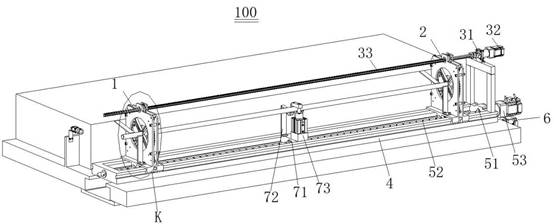
[0035] Such as figure 1 , figure 2 and Figure 8 As shown, the present embodiment provides a tubular workpiece synchronous rotation clamping mechanism, the tubular workpiece synchronous rotation...


PUM


Abstract

The invention provides a tubular workpiece synchronous rotating and clamping mechanism and a welding system based on visual inspection. The tubular workpiece synchronous rotating and clamping mechanism comprises a first clamp, a second clamp, a driving mechanism and a sliding rail base. The first clamp and the second clamp are movably arranged on the sliding rail seat, the sliding rail seat extends in the axial direction of the tubular workpiece, and a clamping opening of the first clamp is opposite to a clamping opening of the second clamp in the axial direction of the tubular workpiece; the first clamp and the second clamp are connected with the driving mechanism, and the driving mechanism is used for synchronously controlling the clamping opening of the first clamp and the clamping opening of the second clamp to be switched between the first state and the second state. According to the device, tubular workpieces with different lengths and different pipe diameters can be conveniently clamped, it is ensured that the tubular workpieces synchronously rotate along with an automatic girth welding machine in a horizontal posture, and the girth welding quality is conveniently ensured by conducting visual inspection on the to-be-welded ends of the tubular workpieces before girth welding and recognizing the diameter and pipe wall defects.

Description

technical field [0001] The invention relates to the field of welding technology, in particular to a tubular workpiece synchronously rotating clamping mechanism and a welding system based on visual inspection. Background technique [0002] Currently, circular seam welding is usually used for welding tubular workpieces. For example, circular seam welding can be used to weld opposite ends of two steel pipes, or to weld opposite ends of a steel pipe and a tubular end plug. Among them, circular seam welding is aimed at the welding of various circular and circular welds, and the weld formed by welding is a closed circular ring. [0003] In practical application, girth welding is realized by automatic girth welding machine. Automatic circular seam welding machine is a general automatic welding equipment that can complete various circular and circular seam welding. However, for different types of tubular workpieces, the automatic girth welding machine is often unable to automatica...

Claims


Application Information

Patent Timeline
Patent Type & Authority Applications(China)
IPC IPC(8): B23K37/053B23K37/00
CPCB23K37/053B23K37/00
Inventor 王禹刘聪李金平曲佳佳单飞虎齐振国王永健李春喜
Owner 北京东方国信科技股份有限公司
Why Eureka
Try Eureka