Automatic mechanical cutting device and using method thereof

A technology of mechanical cutting and cutting table, applied in the direction of metal processing, etc., can solve the problems of mismatching, different workpiece sizes, time waste, etc., and achieve the effect of deepening the accuracy

Inactive Publication Date: 2022-03-11
CHONGQING COLLEGE OF ELECTRONICS ENG
View PDF0 Cites 0 Cited by
  • Summary
  • Abstract
  • Description
  • Claims
  • Application Information

AI Technical Summary

Problems solved by technology

[0002] For the workpiece in the factory or workshop, when using the workpiece, the size of the workpiece may be different from the required size, that is, the mismatch is not applicable, and then the operator will use a certain machine or tool to cut and shape the workpiece. Use; for some small workpieces, the workpiece is cut by a large mechanical or human cutting tool. Among them, large mechanical cutting or cutting by the human power of the tool is inconvenient, that is, the cutting of large utensils is relatively difficult. Small materials are easy to waste time, and manual operation of knives is easy to reduce the efficiency of cutting materials

Method used


Image

  • Automatic mechanical cutting device and using method thereof
  • Automatic mechanical cutting device and using method thereof
  • Automatic mechanical cutting device and using method thereof

Examples


Embodiment 1

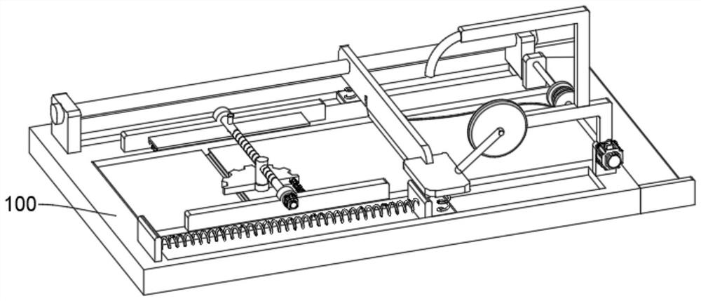
[0054] see Figure 1-Figure 8 As shown, the purpose of this embodiment is to provide an automatic mechanical cutting device, including a cutting mechanism 100, and the cutting mechanism 100 at least includes:

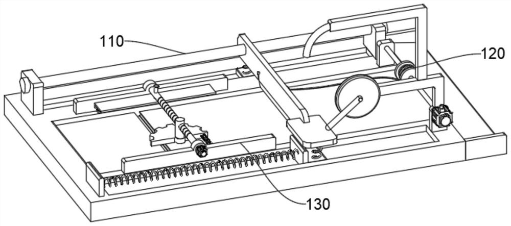
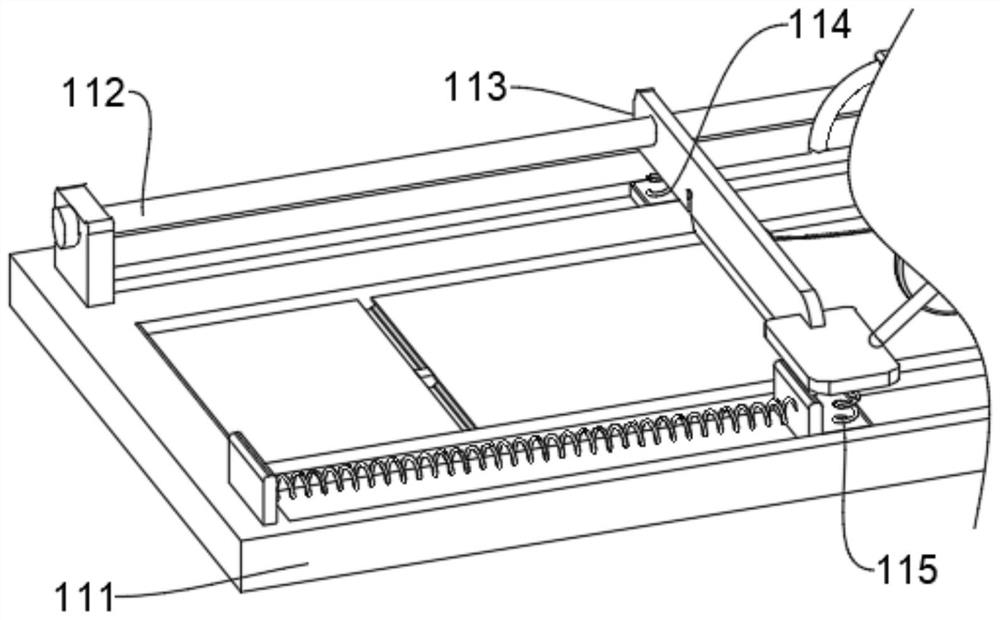
[0055] Cutting body 110, cutting body 110 comprises the rectangular cutting table 111 that opening upwards, on the surface of cutting table 111, the block plate that end portion is arranged symmetrically is equipped with fixed rod 112, and the surface of fixed rod 112 is connected with knife rest 113 in rotation, and knife rest The inside of 113 is provided with a cutting knife 1132, and one end of the knife holder 113 is equipped with a knife handle 1134, and a return plate 115 is installed below the knife handle 1134 via an upper spring 1151, and the upper spring 1151 is used to squeeze and rise the knife handle 1134. ;

[0056] The automatic transmission body 120, the automatic transmission body 120 is installed on an end of the knife rest 113, the automatic transmi...

Embodiment 2

[0062] In order to process the cut material to prevent accumulation from affecting re-cutting, the difference between this embodiment and embodiment 1 is that please refer to Figure 7 and Figure 9 Shown:

[0063] Wherein, the bottom of fixed frame 121 is provided with symmetrical mounting plate 125, and wherein one mounting plate 125 is fixedly installed with fixed frame 121, is rotatably connected by rotating rod 126 between mounting plate 125, and the surface end of rotating rod 126 is provided with surface The runner 127 that is wound with fixed rope 1271, one end of fixed rope 1271 is fixedly connected with knife rest 113 through fixed ring 1272, and one end of rotating rod 126 is connected with rotating rod motor 128 in rotation, when knife rest 113 carries out upward transmission, The fixed rope 1271 is formed to rotate and release the fixed rope 1271 through the rotation of the runner 127 and the rotating rod 126. After the cutting work is completed, the material aft...

Embodiment 3

[0066] In order to perform preliminary position adjustment and positioning on the cutting material, the difference between this embodiment and Embodiment 1 is that please refer to Figure 4 , Figure 10 and Figure 11 Shown:

[0067] Wherein, the other end of the surface of the cutting table 111 is provided with a shape finishing mechanism 130, and the shape finishing mechanism 130 includes an end plate 131 which is fixed and installed symmetrically with the surface of the cutting table 111. One end of 132 is rotatably connected with a screw motor 1321, and the rotation shaft connected by surface threads is rotatably connected with a finishing wheel 133 under the screw 132. Considering that for material workpieces, how long is the material or level after stacking at the same time? Placed multiple materials for cutting, because the materials are prone to shaking on the surface of the horizontal cutting table 111, such as plastic tubes, mechanical grinding paper or sandpaper, ...


PUM


Abstract

The invention relates to the technical field of cutting devices, in particular to an automatic mechanical cutting device and a using method thereof. The device comprises a cutting mechanism, the cutting mechanism at least comprises a cutting body, the cutting body comprises a cutting table, a fixing rod is installed on the surface of the cutting table through block plates symmetrically arranged at the ends, the surface of the fixing rod is rotationally connected with a tool rest, a cutting tool is arranged in the tool rest, a tool handle is installed at one end of the tool rest, and a return plate is installed below the tool handle through an upper spring; and the automatic transmission body comprises a fixing frame installed on the cutting table, one end of the fixing frame is rotationally connected with a wheel disc, one end face of the wheel disc is rotationally connected with a wheel disc motor, and a guide rod is installed at one end of the surface of the wheel disc. According to the automatic material cutting device, automatic material cutting operation can be conducted on small or fragile materials, manpower is saved, and waste of resources is reduced.

Description

technical field [0001] The present invention relates to the technical field of a cutting device, in particular to an automatic mechanical cutting device and a method for using the same. Background technique [0002] For the workpiece in the factory or workshop, when using the workpiece, the size of the workpiece may be different from the required size, that is, the mismatch is not applicable, and then the operator will use a certain machine or tool to cut and shape the workpiece. Use; for some small workpieces, the workpiece is cut by a large mechanical or human cutting tool. Among them, large mechanical cutting or cutting by the human power of the tool is inconvenient, that is, the cutting of large utensils is relatively difficult. Small materials are easy to waste time, and manual operation of knives is easy to reduce the efficiency of cutting materials. In view of this, we propose an automatic mechanical cutting device and its use method to solve the existing problems. ...

Claims


Application Information

Patent Timeline
Patent Type & Authority Applications(China)
IPC IPC(8): B26D1/06B26D5/08B26D7/08B26D7/18
CPCB26D1/06B26D1/065B26D5/08B26D7/1818B26D7/08
Inventor 孙文成谢光辉谢灿陈甫赵鹏举杨仁强刘小瑞李书阁
Owner CHONGQING COLLEGE OF ELECTRONICS ENG
Why Eureka
Try Eureka