A laser current drive circuit and drive method with maximum current protection

A technology of current drive and maximum current, which is applied to emergency protection circuit devices, emergency protection circuit devices, lasers, etc. for limiting overcurrent/overvoltage, and can solve problems such as response lag and insufficient current setting accuracy to improve safety. Unique, easy to implement, and high-precision effects

Active Publication Date: 2020-03-10
ACCELINK ELECTRONICS TECH
View PDF9 Cites 0 Cited by
  • Summary
  • Abstract
  • Description
  • Claims
  • Application Information

AI Technical Summary

Problems solved by technology

[0005] The technical problem to be solved by the present invention is to solve the problems of response lag and current setting accuracy existing in the existing laser current-driven backward feedback protection technology

Method used


Image

  • A laser current drive circuit and drive method with maximum current protection
  • A laser current drive circuit and drive method with maximum current protection
  • A laser current drive circuit and drive method with maximum current protection

Examples


Embodiment 1

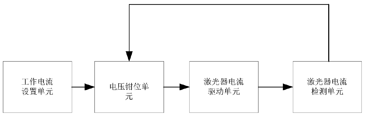
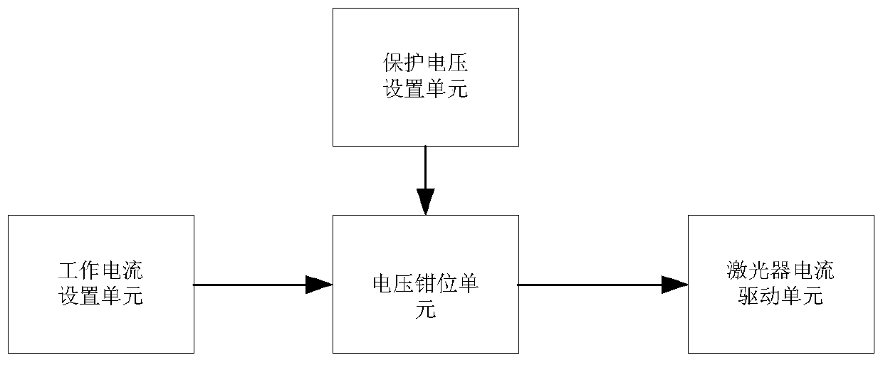
[0053] Embodiment 1 of the present invention provides a laser current drive circuit with maximum current protection, such as image 3 As shown, it includes a working current setting unit, a voltage clamping unit, a protection voltage setting unit and a laser current driving unit, wherein the working current setting unit, the protection voltage setting unit and the laser current driving unit are respectively connected to the voltage clamping unit, specific:

[0054] The protection voltage setting unit is used to set the reference protection voltage for the voltage clamping unit as a basis for comparison; wherein, the reference protection voltage value is calculated according to the maximum current allowed by the laser;

[0055] The voltage clamping unit is used to obtain the reference protection voltage of the protection voltage setting unit, and by comparing the input quantity of the working current setting unit, determine that the output to the laser current driving unit is t...

Embodiment 2

[0069] After the present invention provides the laser current drive circuit with maximum current protection described in Embodiment 1, the present invention also provides a laser current drive method with maximum current protection. The principle of laser current drive circuit with maximum current protection, specifically:

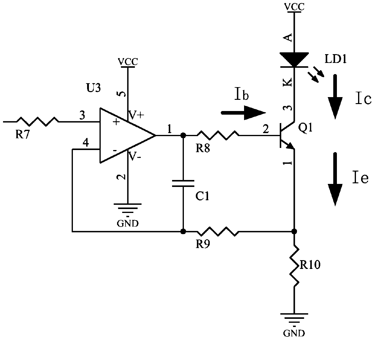
[0070] When the output voltage Vin At this time, the voltage clamping unit is in a normal working state, and the output Vin of the laser LD1 driving current I and the current setting unit are in accordance with the proportional coefficient Corresponding change; wherein, Vmax is the output of the protection voltage setting unit and the reference protection voltage of the voltage clamping unit; the resistor R8 is a resistor connected between the collector of the transistor Q1 and the positive input port of the operational amplifier U3;

[0071] When the output voltage Vin of the working current setting unit is > 2Vmax, the output voltage Vo1 of the operatio...

Embodiment 3

[0087] Based on the laser current drive circuit with maximum current protection described in Embodiment 1, the embodiment of the present invention further elaborates the optimal setting of supporting parameters and the corresponding implementation process in a specific application scenario.

[0088] Include the complete drive circuit diagram of the improvement point of the present invention, as Image 6 As shown, the current I1 is the current flowing through the resistor R8, the current I2 is the current flowing through the resistor R10, and the current I is the current flowing through the laser LD1 and the sampling resistor RS. Between the output terminal of the integrating capacitor C1 and the inverting input terminal, the value of C1 is 100pF, and the value of R1 is 1K. The function of C1 can limit the bandwidth of the current drive unit to around 1MHz, and at the same time, it is used to force the op amp between the non-inverting terminal and the inverting terminal The vol...


PUM


Abstract

The invention relates to the technical field of semiconductor laser driving, and provides a laser current driving circuit with maximum current protection and a driving method. Wherein the circuit comprises a protection voltage setting unit for setting a reference protection voltage according to which the supply voltage clamping unit is used as a comparison basis; Wherein, the reference protectionvoltage value is calculated according to the maximum permissible current of the laser; The voltage clamping unit is configured to obtain a reference protection voltage of the protection voltage setting unit, and determine whether the output amount of the working current setting unit or the clamping voltage clamped by the voltage clamping unit is output to the laser current driving unit by comparing the input amount of the working current setting unit. The circuit structure of the invention is simple, because the intervention of the external main controller is not required, the precision is higher, the realization is easy, and only a few components need to be added, so that the laser can be remarkably protected, and the safety, the stability and the precision of the system are improved.

Description

【Technical field】 [0001] The invention relates to the field of semiconductor laser drive technology, in particular to a laser current drive circuit and a drive method with maximum current protection. 【Background technique】 [0002] Such as figure 1 As shown, the traditional semiconductor laser drive circuit protects the laser by comparing the actual current of the load with the maximum protection current. This is a kind of backward feedback protection. The disadvantage of this protection method is the response lag. When the protection action occurs, the overcurrent has actually occurred, and the load may have been damaged. [0003] Another traditional semiconductor laser drive circuit such as figure 2 As shown, the disadvantage of this drive circuit is that the laser is placed on the collector of the triode, and the sampling resistor is placed on the emitter of the triode. According to Kirchhoff's current law, the emitter current Ie=Ic+Ib of the triode, which is It will ...

Claims


Application Information

Patent Timeline
Patent Type & Authority Patents(China)
IPC IPC(8): H01S5/042H02H9/04
CPCH01S5/042H02H9/04
Inventor 李春雨陈俊余春平
Owner ACCELINK ELECTRONICS TECH
Why Eureka
Try Eureka