Check patentability & draft patents in minutes with Patsnap Eureka AI!

A kind of asynchronous control method of digital valve

An asynchronous control, digital valve technology, applied in the valve operation/release device, valve device, valve details and other directions, can solve the problems of digital valve flow shock, to solve the flow shock problem, ensure long-term stable operation, and prolong the use of equipment effect of life

Active Publication Date: 2022-04-12
LOW SPEED AERODYNAMIC INST OF CHINESE AERODYNAMIC RES & DEV CENT
View PDF13 Cites 0 Cited by
  • Summary
  • Abstract
  • Description
  • Claims
  • Application Information

AI Technical Summary

Problems solved by technology

[0005] The purpose of the present invention is to propose an asynchronous control method for digital valves to solve the problem of flow impact caused by switching digital valves in the actual control process

Method used


Image

  • A kind of asynchronous control method of digital valve
  • A kind of asynchronous control method of digital valve
  • A kind of asynchronous control method of digital valve

Examples


Embodiment Construction

[0037] All features disclosed in this specification, or steps in all methods or processes disclosed, may be combined in any manner, except for mutually exclusive features and / or steps.

[0038] Any feature disclosed in this specification (including any appended claims, abstract and drawings), unless expressly stated otherwise, may be replaced by alternative features which are equivalent or serve a similar purpose. That is, unless expressly stated otherwise, each feature is one example only of a series of equivalent or similar features.

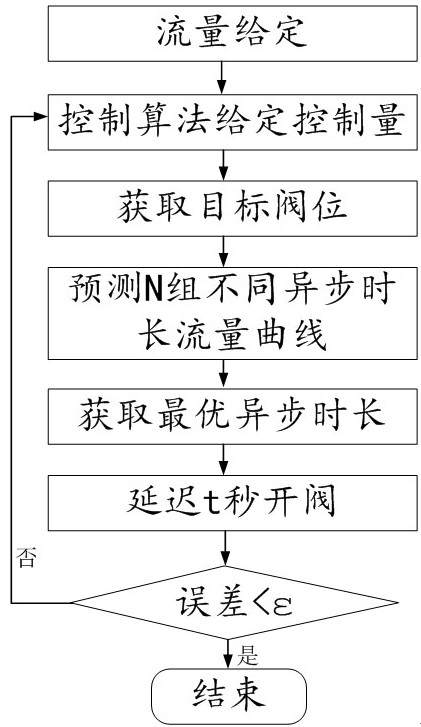
[0039] Such as figure 1 Shown is a schematic flow chart of the control method. The control method of this embodiment includes three steps: predicting the actual flow curve based on the digital valve step response, selecting the optimal asynchronous time for valve switching based on the cost function, and delaying the opening of the valve according to the optimal asynchronous time. .

[0040] First, the actual flow curve is predicted based ...


PUM


Abstract

The invention discloses an asynchronous control method of a digital valve, which comprises three steps: predicting the actual flow curve based on the step response of the digital valve, selecting the optimal asynchronous time length for valve switching based on a cost function, and delaying valve opening according to the optimal asynchronous time length. In the asynchronous control method, the valve closing signal is given first, and after a period of delay, the valve opening signal is given, which fundamentally solves the flow impact problem caused by digital valve switching. This method obtains the asynchronous control duration through the numerical simulation of the step response between the valve groups, instead of measuring the response duration of specific valves separately at a certain pressure, which can effectively avoid the response of each valve under the influence of the pressure difference caused by different high-pressure airflows. The control effects brought about by different durations. This technology was used for the first time in the digital valve flow control of the wind tunnel test, which solved the problem of flow shock caused by digital valve switching and the problem of some flow target point control oscillations.

Description

technical field [0001] The invention relates to the field of experimental aerodynamics, in particular to an asynchronous control method of a digital valve. Background technique [0002] In aerodynamic experiments, jet flow simulation, power component drive, etc. all need to use high-pressure gas. During use, the flow control of high-pressure gas is very important. The digital valve has the characteristics of wide adjustable range, high control precision, fast response speed, simple structure, strong robustness, and high reliability. The digital valve is mainly composed of a Venturi nozzle and a pilot solenoid valve arranged and combined according to the binary law. The system first controls the on-off of each pipeline by switching different solenoid valves to achieve the purpose of combining different flows. [0003] Although digital valves have been widely used in the field of experimental aerodynamics, in the actual use process, it is found that there is a problem of flo...

Claims


Application Information

Patent Timeline
Patent Type & Authority Patents(China)
IPC IPC(8): F16K31/00G06F17/11G01M9/00F16K31/06
CPCF16K31/00G06F17/11G01M9/00F16K31/06
Inventor 陈旷何苗章荣平晋荣超
Owner LOW SPEED AERODYNAMIC INST OF CHINESE AERODYNAMIC RES & DEV CENT
Features
  • R&D
  • Intellectual Property
  • Life Sciences
  • Materials
  • Tech Scout
  • Unparalleled Data Quality
  • Higher Quality Content
  • 60% Fewer Hallucinations
Learn More