Supercharge Your Innovation With Domain-Expert AI Agents!

Bottom baffling type two-way oxygen supply pyrolysis gasification furnace for plateau

A pyrolysis gasification and baffle technology, applied in incinerators, lighting and heating equipment, combustion methods, etc., can solve problems such as odor air pollution, soil pollution, and affecting the quality of pyrolysis gasification, achieving secondary Complete combustion, improve the quality of pyrolysis and gasification, and improve the effect of distribution range

Pending Publication Date: 2022-03-11
夏宇
View PDF0 Cites 0 Cited by
  • Summary
  • Abstract
  • Description
  • Claims
  • Application Information

AI Technical Summary

Problems solved by technology

[0002] Nowadays, the amount of urban domestic waste is increasing day by day. How to effectively dispose of these domestic wastes has become a top priority. The more common methods of disposal include landfill and incineration. However, the landfill treatment occupies a large area, and the seepage produced by improper disposal not only affects the soil, Groundwater causes serious pollution, and the odor produced by its fermentation will also pollute the air; although the use of incineration reduces the occupied area, it will also release a large amount of foul smell and even poisonous gas during the incineration process. There are also a lot of dust and fine particles, which will also cause damage to the environment.
At present, another treatment method is pyrolysis gasification, which mainly uses pyrolysis gasification furnace to pyrolysis gasify combustible domestic waste. Compared with landfill and incineration, pyrolysis gasification has high harmless conversion rate and secondary The advantages of small pollution, among which the pyrolysis method includes direct heating method and indirect heating method, direct heating method: the heat supplied to the pyrolyzed matter is part of the pyrolyzed matter (processed waste) to be directly burned or gasified to pyrolysis The heat generated when the furnace provides supplementary fuel, because the combustion needs to provide oxygen to support the combustion, first use air, oxygen-enriched or pure oxygen to support the combustion, but in the plateau area, the oxygen content is low, directly put the domestic waste into the pyrolysis gasifier Combustion in the middle is likely to cause insufficient combustion and affect the quality of pyrolysis gasification

Method used


Image

  • Bottom baffling type two-way oxygen supply pyrolysis gasification furnace for plateau
  • Bottom baffling type two-way oxygen supply pyrolysis gasification furnace for plateau
  • Bottom baffling type two-way oxygen supply pyrolysis gasification furnace for plateau

Examples


Embodiment 1

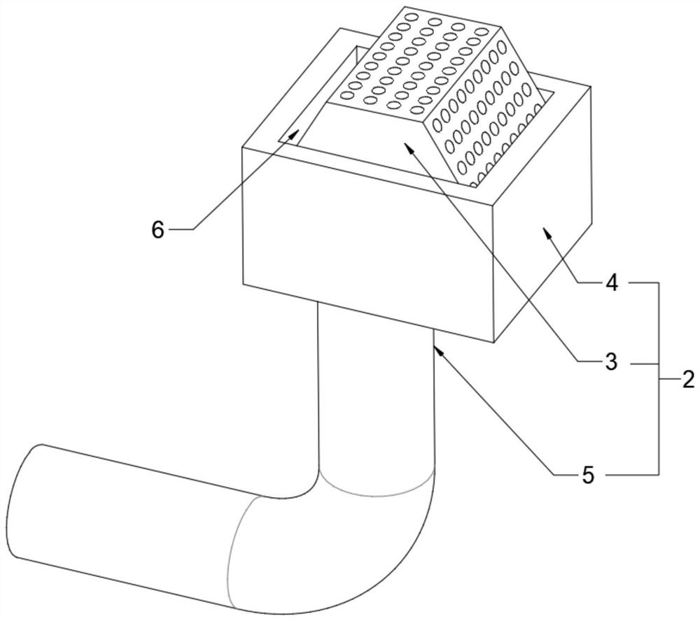
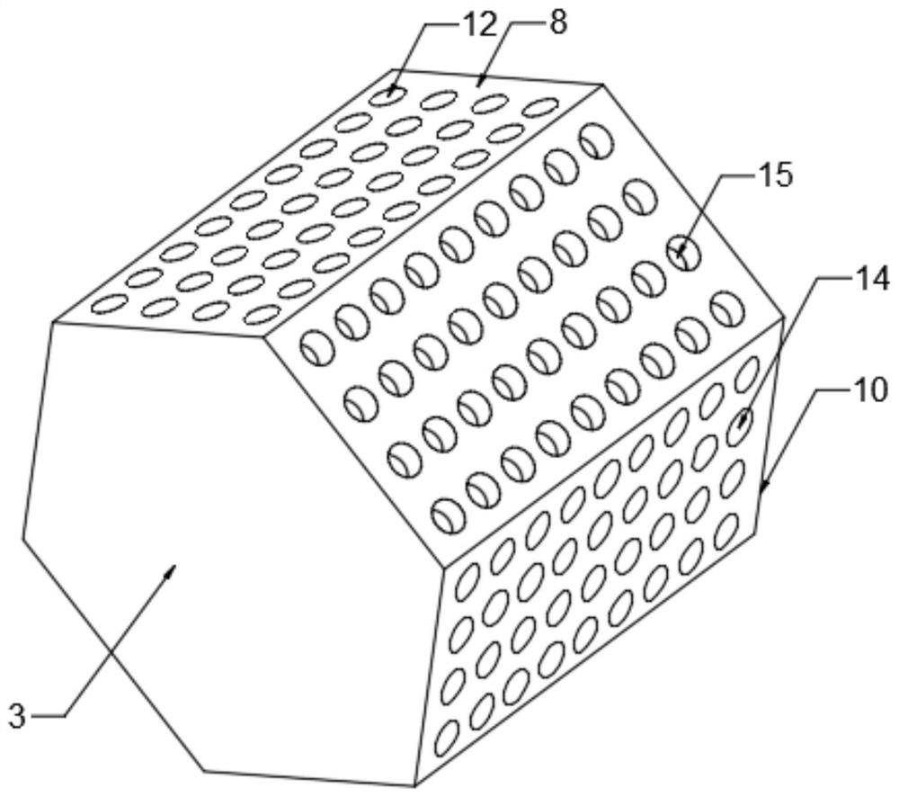
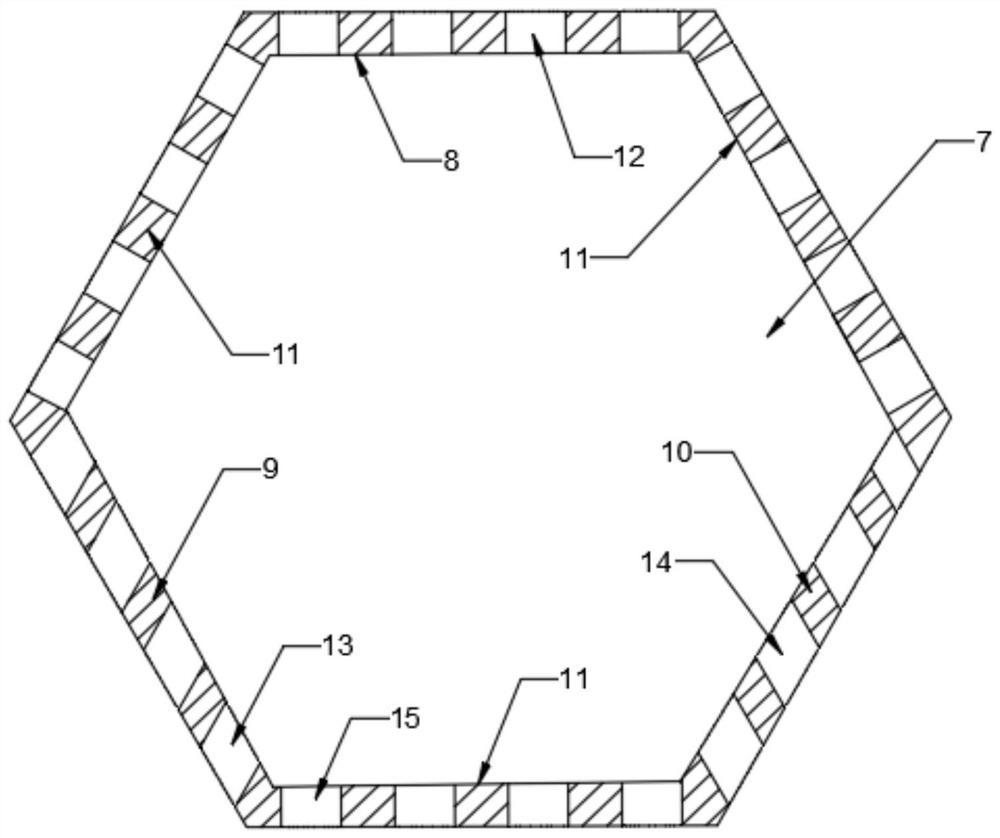
[0027] Embodiment one, as Figure 1 to Figure 3As shown, a bottom baffle type bidirectional oxygen supply pyrolysis gasifier for the plateau includes a gasification furnace body 1 and an oxygen supply assembly 2, and the oxygen supply assembly 2 is arranged in the gasification furnace body 1, The oxygen supply assembly 2 includes a rotating oxygen supply block 3, an oxygen supply housing 4 and an oxygen supply pipeline 5. The oxygen supply housing 4 is provided with a rotating chamber 6 with an open top, and the rotating oxygen supply block 3 is rotatably arranged in the rotating chamber 6. The oxygen supply pipeline 5 is fixedly installed on the gasifier body 1, one end of the oxygen supply pipeline 5 is connected to the bottom of the oxygen supply shell 4, and the oxygen supply pipeline 5 communicates with the rotating chamber 6; the shape of the rotating oxygen supply block 3 is six The two ends of the prism and the rotating oxygen supply block 3 are rotatably connected wit...

Embodiment 2

[0029] Embodiment two, such as Figure 4 and Figure 5 As shown, the furnace body 1 of the gasifier is provided with a furnace bridge 24. The furnace bridge 24 is located below the oxygen supply shell 4. The furnace bridge 24 includes a furnace bridge frame 25 and two sets of furnace bridge mechanisms 26. On the inner wall of the furnace body 1, two groups of furnace bridge mechanisms 26 are arranged on the furnace bridge frame 25 at intervals, and an oxygen supply gap 27 for the oxygen supply pipeline 5 to pass is formed between the two groups of furnace bridge mechanisms 26, and the oxygen supply gap 27 The width of the furnace bridge mechanism 26 includes a plurality of first rotating shafts 28 and a plurality of second rotating shafts 29, and the first rotating shafts 28 and the second rotating shafts 29 are alternately arranged. The first rotating shaft 28 and the second rotating shaft 29 are rotatably connected to the furnace bridge 25 through bearings. The rotating dir...

Embodiment 3

[0031] Embodiment three, as Figure 7 As shown, the top of the gasifier body 1 is connected with a gas outlet pipe 37, the gas outlet pipe 37 is connected with a temporary storage box 38, the temporary storage box 38 is connected with an exhaust pipe 39, and the gas outlet pipe 37 is provided with a gas path check valve. 40. The exhaust pipe 39 is provided with a switch valve 41; the gas generated by the burning of garbage enters the temporary storage box 38 through the air outlet pipe 37. Since the gas circuit check valve 40 can only be conducted in one direction, the gas can only pass through the outlet pipe. The gas pipe 37 enters the temporary storage box 38 and cannot flow into the gasification furnace body 1 from the temporary storage box 38. The gas is temporarily stored through the temporary storage box 38, and the switch valve 41 is opened to make the gas in the temporary storage box 38 flow from Exhaust pipe 39 is discharged for use.


PUM


Abstract

The bottom baffling type two-way oxygen supply pyrolysis gasification furnace comprises a gasification furnace body and an oxygen supply assembly, the oxygen supply assembly is arranged in the gasification furnace body and comprises a rotary oxygen supply block, an oxygen supply shell and an oxygen supply pipeline, and a rotary cavity with an opening in the top is formed in the oxygen supply shell; the rotary oxygen supply block is rotationally arranged in the rotary cavity, and one end of the oxygen supply pipeline is connected with the bottom of the oxygen supply shell; the rotary oxygen supply block is in a hexagonal prism shape and comprises a straight air outlet side plate, a left air outlet side plate, a right air outlet side plate and three straight air inlet side plates, two of the straight air inlet side plates are connected with the two ends of the straight air outlet side plate respectively, and the other straight air inlet side plate is located on the opposite side of the straight air outlet side plate. Oxygen is introduced into the gasification furnace body in different directions through the rotating rotary oxygen supply block, so that the oxygen is widely distributed in the gasification furnace body, the distribution range of the oxygen is widened, garbage subjected to secondary combustion is in full contact with the oxygen, secondary combustion is more sufficient, and the pyrolysis gasification quality is improved.

Description

technical field [0001] The invention relates to the technical field of pyrolysis and gasification furnaces, in particular to a pyrolysis and gasification furnace with bottom baffle type bidirectional oxygen supply for plateaus. Background technique [0002] Nowadays, the amount of urban domestic waste is increasing day by day. How to effectively dispose of these domestic wastes has become a top priority. The more common methods of disposal include landfill and incineration. However, the landfill treatment occupies a large area, and the seepage produced by improper disposal not only affects the soil, Groundwater causes serious pollution, and the odor produced by its fermentation will also pollute the air; although the use of incineration reduces the occupied area, it will also release a large amount of foul smell and even poisonous gas during the incineration process. There is also a large amount of dust and fine particles, which will also cause damage to the environment. At...

Claims


Application Information

Patent Timeline
Patent Type & Authority Applications(China)
IPC IPC(8): F23G5/027F23G5/14F23G5/033F23G5/44
CPCF23G5/027F23G5/14F23G5/033F23G5/44F23G2201/302F23G2201/303F23G2201/80
Inventor 夏宇
Owner 夏宇
Features
  • R&D
  • Intellectual Property
  • Life Sciences
  • Materials
  • Tech Scout
  • Unparalleled Data Quality
  • Higher Quality Content
  • 60% Fewer Hallucinations
Learn More