Optical fiber fusion receiving box

An optical fiber and fusion splicing technology, which is applied in the field of optical fiber sensing equipment, can solve the problems of not being able to neatly coil the optical fiber and the use of space is too large, and achieve the effect of clear layers and large capacity.

Pending Publication Date: 2022-03-11
SUZHOU GUANGGE EQUIP
View PDF0 Cites 0 Cited by
  • Summary
  • Abstract
  • Description
  • Claims
  • Application Information

AI Technical Summary

Problems solved by technology

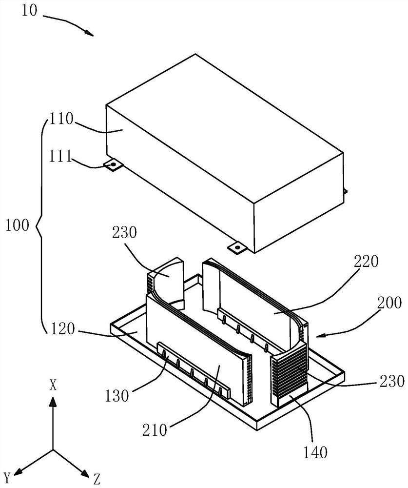
[0004] Based on this, it is necessary to provide an optical fiber melting and receiving box that can not only neatly coil the optical fiber but also to solve the shortcomings of the existing optical fiber fusion receiving box that cannot neatly coil the optical fiber, and the fiber winding radius is too large, resulting in too large space for the optical fiber fusion receiving box. More effective use of the space of the fiber fusion receiving box, and can be compatible with a large number of optical fiber fusion receiving box

Method used


Image

  • Optical fiber fusion receiving box
  • Optical fiber fusion receiving box
  • Optical fiber fusion receiving box

Examples


Embodiment Construction

[0025] In order to make the above objects, features and advantages of the present invention more comprehensible, specific implementations of the present invention will be described in detail below in conjunction with the accompanying drawings. In the following description, numerous specific details are set forth in order to provide a thorough understanding of the present invention. However, the present invention can be implemented in many other ways different from those described here, and those skilled in the art can make similar improvements without departing from the connotation of the present invention, so the present invention is not limited by the specific embodiments disclosed below.

[0026] It should be noted that when an element is referred to as being “fixed” to another element, it can be directly on the other element or there can also be an intervening element. When an element is referred to as being "connected to" another element, it can be directly connected to t...


PUM


Abstract

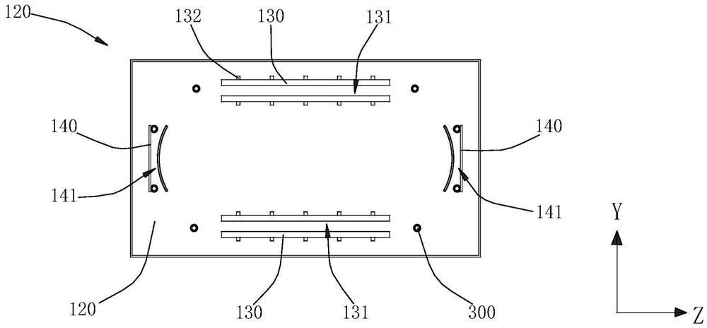
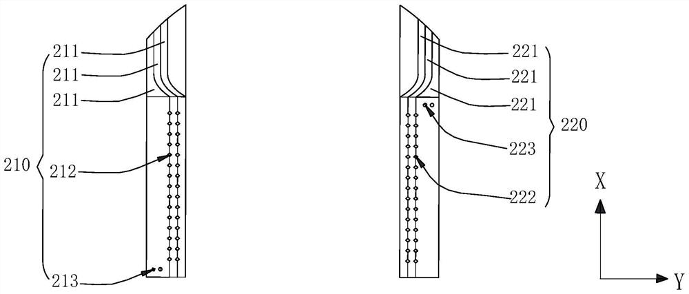
The invention relates to an optical fiber fusion receiving box which comprises a shell and a support, the shell is provided with a containing cavity, the support is installed in the shell and contained in the containing cavity, the support is provided with a fiber passing channel used for containing optical fibers, the fiber passing channel is provided with a wire inlet hole and a wire outlet hole which are communicated with each other, and the inner diameter of the fiber passing channel is matched with the outer diameter of one optical fiber. A single optical fiber can penetrate through the fiber passing channel, and the optical fiber penetrating through the fiber passing channel extends spirally, so that each layer of optical fiber penetrates through the corresponding fixed fiber passing hole when the optical fiber is spirally wound on the support, the phenomenon that a large number of optical fibers are wound together to be knotted or loosened is avoided, meanwhile, the optical fibers are wound on the support in a layered mode in the vertical direction, and the optical fiber winding efficiency is improved. The optical fiber fusion receiving box is clear in layering, makes full use of the space, and can be compatible with all optical fibers of one device.

Description

technical field [0001] The invention relates to the technical field of optical fiber sensing equipment, in particular to an optical fiber fusion receiving box. Background technique [0002] With the development of communication technology, optical communication equipment has become the current main communication equipment, and optical communication equipment is generally connected by optical fiber. At present, optical fiber fusion splicing and fixed placement usually use optical fiber fusion receiving boxes, and optical fibers are coiled into a circle and stored in the optical fiber fusion receiving box. [0003] The existing optical fiber fusion receiving box usually does not have the feature of conveniently coiling the optical fiber, and can only simply coil the optical fiber. Specifically, some optical fiber fusion receiving boxes do not have a limit structure, and the optical fibers are only fixed with tape or cable bridges and then coiled in the optical fiber fusion re...

Claims


Application Information

Patent Timeline
Patent Type & Authority Applications(China)
IPC IPC(8): G02B6/255
CPCG02B6/255
Inventor 谭宏洋王宏飞姜明武
Owner SUZHOU GUANGGE EQUIP
Why Eureka
Try Eureka