Cutting tool

A technology of cutting tools and unit layers, which is applied in the direction of manufacturing tools, workpieces, drilling accessories, etc., and can solve problems such as cutting edge wear

Pending Publication Date: 2022-03-11
SUMITOMO ELECTRIC HARDMETAL CORP
View PDF5 Cites 0 Cited by
  • Summary
  • Abstract
  • Description
  • Claims
  • Application Information

AI Technical Summary

Problems solved by technology

Such cutting tools are exposed to severe environments such as high temperature and high stress during cutting, which leads to wear and chipping of the cutting edge

Method used


Image

  • Cutting tool
  • Cutting tool
  • Cutting tool

Examples


Embodiment

[0185] Hereinafter, although an Example is given and this invention is demonstrated in detail, this invention is not limited to these Examples.

[0186] "Making of Cutting Tools"

[0187]

[0188] First, as a substrate to be coated, substrates made of cemented carbide shown in Table 1 below (hereinafter, may be simply referred to as “substrates”) were prepared (first step). Specifically, first, raw material powders having a mixing composition (mass %) described in Table 1 were uniformly mixed. "Remainder" in Table 1 indicates that WC occupies the remainder of the mixed composition (mass %).

[0189] [Table 1]

[0190]

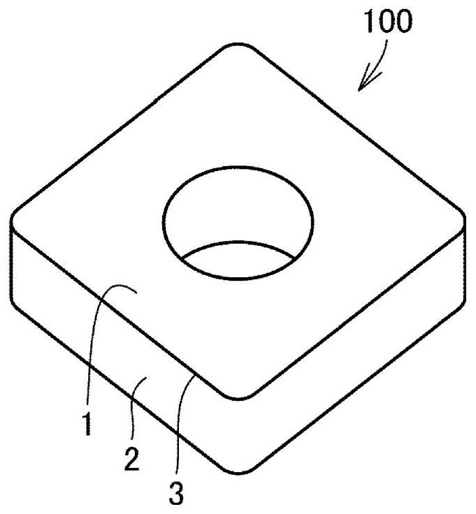
[0191] Next, the mixed powder was press-molded into a predetermined shape, and then sintered at 1300-1500° C. for 1-2 hours to obtain the above-mentioned substrate (substrate shape (JIS standard): SEET13T3AGSN-G). It should be noted that SEET13T3AGSN-G is the shape of an indexable cutting insert for milling.

[0192]

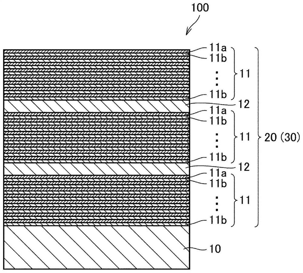
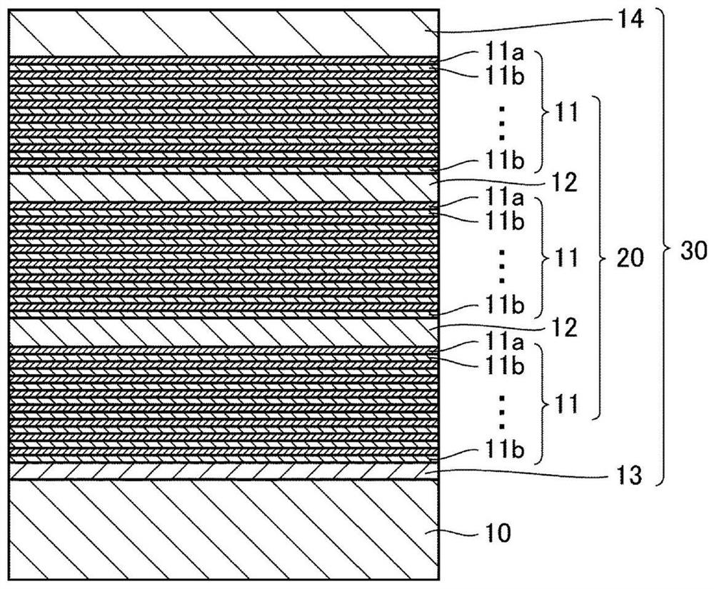
[0193] By forming the base laye...


PUM

PropertyMeasurementUnit
thicknessaaaaaaaaaa
thicknessaaaaaaaaaa
thicknessaaaaaaaaaa

Abstract

A cutting tool includes a base material, and a coating layer provided on the base material, the coating layer including a multilayer structure layer comprising a first unit layer and a second unit layer, and an individual layer containing cubic TizAl1-zN crystal grains, the atomic ratio z of Ti in the TizAl1-zN being 0.4 or more and less than 0.55, and the atomic ratio z of Ti in the TizAl1-zN being 0.4 or more and less than 0.55. The average value of the thicknesses of the individual layers is 2.5 nm to 10 nm, the average value of the thicknesses of the multilayer structure layer is 10 nm to 45 nm, the average value of the thicknesses of the repeating units composed of one multilayer structure layer and one individual layer is 20 nm to 50 nm, the maximum value of the thickness of the repeating units is 40 nm to 60 nm, and the average value of the thicknesses of the repeating units composed of one multilayer structure layer and one individual layer is 10 nm to 45 nm. The minimum value of the thickness of the repeating units is 10 nm or more and 30 nm or less.

Description

technical field [0001] The present disclosure relates to cutting tools. This application claims priority based on Japanese Patent Application Japanese Patent Application No. 2019-186820 filed on October 10, 2019. All the content described in this Japanese patent application is incorporated in this specification by reference. Background technique [0002] Conventionally, cutting of steel, castings, and the like has been performed using cutting tools made of cemented carbide or cubic boron nitride sintered body (cBN sintered body). During the cutting process of such a cutting tool, the cutting edge is exposed to severe environments such as high temperature and high stress, which leads to wear and chipping of the cutting edge. [0003] Therefore, it is important to suppress the wear and chipping of the cutting edge to improve the cutting performance of the cutting tool and increase the life of the cutting tool. [0004] In order to improve the cutting performance (for exampl...

Claims


Application Information

Patent Timeline
Patent Type & Authority Applications(China)
IPC IPC(8): B23D79/00
CPCB23D79/00B22F2003/242B22F2005/001C22C29/00C23C16/34C23C16/45508C23C16/45574C23C16/45578C23C28/04C23C28/044C23C28/40C23C28/42C23C30/005B23B27/148B23B2228/105C22C29/08C22C29/16C23C14/0617C23C16/303
Inventor 城户保树阿侬萨克·帕索斯奥野晋
Owner SUMITOMO ELECTRIC HARDMETAL CORP
Why Eureka
Try Eureka