Laser module assembly of alignment system, metrology system and lithographic apparatus

A measurement and laser technology, applied in the field of laser module components, which can solve the problems of low magnitude, damage to the alignment position accuracy, etc.

Pending Publication Date: 2022-03-11
ASML HLDG NV
View PDF2 Cites 0 Cited by
  • Summary
  • Abstract
  • Description
  • Claims
  • Application Information

AI Technical Summary

Problems solved by technology

Since many stacks and / or alignment marks are polarized, the light collected from the alignment marks can be of very low magnitude thus compromising the accuracy of the calculated alignment position

Method used


Image

  • Laser module assembly of alignment system, metrology system and lithographic apparatus
  • Laser module assembly of alignment system, metrology system and lithographic apparatus
  • Laser module assembly of alignment system, metrology system and lithographic apparatus

Examples


Embodiment Construction

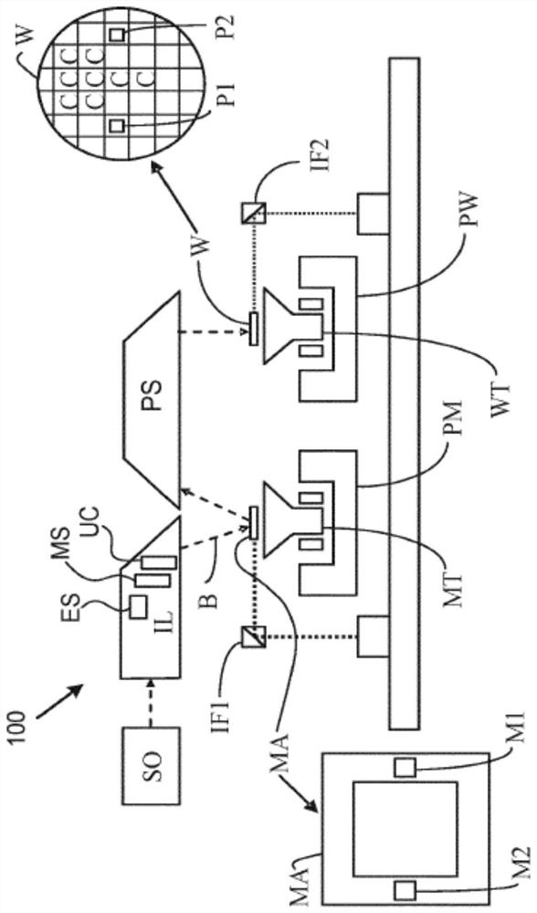
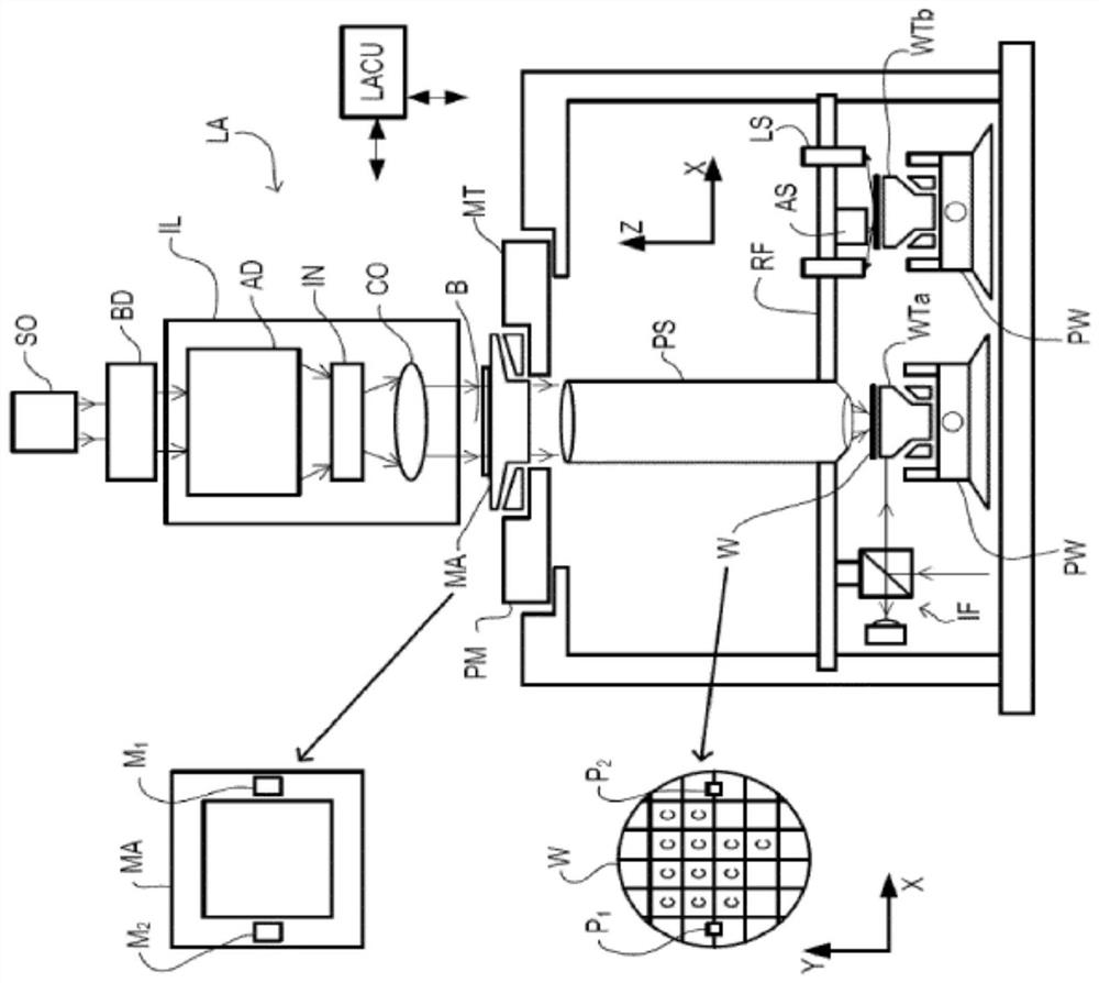
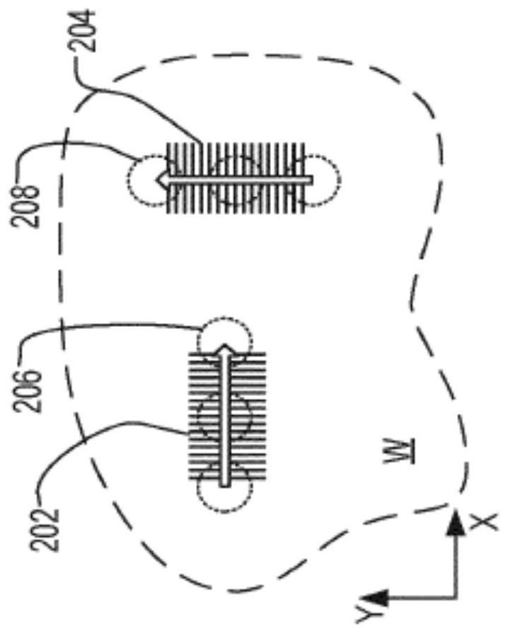
[0038] This specification discloses one or more embodiments that incorporate the features of this invention. The disclosed embodiments are merely illustrative of the invention. The scope of the invention is not limited to the disclosed embodiments. The invention is defined by the appended claims.

[0039]The described embodiments and references in the specification to "one embodiment," "an embodiment," "exemplary embodiment," etc. indicate that the described embodiments may include a particular feature, structure, or characteristic, but each implementation An example may not necessarily include the specific feature, structure or characteristic. Moreover, such phrases are not necessarily referring to the same embodiment. In addition, when a particular feature, structure, or characteristic is described in conjunction with an embodiment, it should be understood that it is within the knowledge of those skilled in the art to implement such feature, structure, or characteristic i...


PUM


Abstract

A metrology system includes a radiation source configured to generate a plurality of light beams, each light beam centered at a different wavelength; a dynamic polarization controller configured to dynamically alternate a polarization orientation of each of the plurality of light beams; a polarization multiplexer configured to combine the plurality of light beams having a dynamically alternating polarization orientation into a combined light beam; a reflector configured to direct the combined light beam toward a substrate; an interferometer configured to receive light that has been diffracted from the pattern on the substrate and to generate output light according to interference between the diffracted light; and a detector configured to detect an optical signal based on output light from the interferometer and output an intensity signal that varies over time.

Description

[0001] Cross References to Related Applications [0002] This application claims priority to US Application 62 / 883,889, filed August 7, 2019, the entire contents of which are incorporated herein by reference. technical field [0003] The present disclosure relates to laser module assemblies used as alignment sources in metrology systems that may be used, for example, in lithographic apparatus. Background technique [0004] A lithographic apparatus is a machine that applies a desired pattern to a target portion of a substrate. For example, lithographic equipment may be used in the manufacture of integrated circuits (ICs). In this case, a patterning device (alternatively referred to as a mask or reticle) can be used to create a circuit pattern corresponding to the individual layers of the IC, and the pattern can be imaged on a layer of radiation-sensitive material (anti- etchant) layer on a substrate (eg a silicon wafer) on a target portion (eg, a portion including a die, on...

Claims


Application Information

Patent Timeline
Patent Type & Authority Applications(China)
IPC IPC(8): G03F9/00
CPCG03F9/7049G03F9/7065G03F9/7046
Inventor M·U·阿高恩卡
Owner ASML HLDG NV
Why Eureka
Try Eureka