
Method for installing dynamic pressure motor and frame assembly

A technology of dynamic pressure motor and installation method, which is applied in the direction of workpiece clamping device, device for coating liquid on the surface, hand-held tool, etc., which can solve the problem of poor stability of gyroscope, different amount of deformation, and unstable center of mass of float components and other problems to achieve the effect of improving stability and preventing thread loosening

Active Publication Date: 2022-03-15
XIAN AEROSPACE PRECISION ELECTROMECHANICAL INST
View PDF9 Cites 4 Cited by
  • Summary
  • Abstract
  • Description
  • Claims
  • Application Information

AI Technical Summary

Problems solved by technology

[0009] The purpose of the present invention is to provide a method for installing an H-type double-stator dynamic voltage motor and a frame assembly, so as to solve the problem of heat generation due to the use of materials with different linear expansion coefficients at the junction of the motor shaft of the H-type double-stator dynamic voltage motor and the frame assembly. Expansion and contraction lead to different deformations, which makes the center of mass of the float assembly unstable, which eventually causes the problem of poor stability of the gyro and the instability of the center of mass of the float assembly due to improper glue application, installation sequence, and glue usage, which eventually causes Problems with poor gyro stability

Method used


Image

  • Method for installing dynamic pressure motor and frame assembly
  • Method for installing dynamic pressure motor and frame assembly
  • Method for installing dynamic pressure motor and frame assembly

Examples


Embodiment Construction

[0054] In order to make the above-mentioned purposes, features and advantages of the present invention more obvious and easy to understand, the specific implementation modes of the present invention will be described in detail below in conjunction with the accompanying drawings. Obviously, the described embodiments are part of the embodiments of the present invention, not all of them. Example. Based on the embodiments of the present invention, all other embodiments obtained by ordinary persons in the art without creative efforts shall fall within the protection scope of the present invention.

[0055] In the following description, a lot of specific details are set forth in order to fully understand the present invention, but the present invention can also be implemented in other ways different from those described here, and those skilled in the art can do it without departing from the meaning of the present invention. By analogy, the present invention is therefore not limited ...


PUM


Abstract

The invention belongs to the technical field of two-floating gyroscope installation and adjustment, and particularly relates to an installation method of a dynamic pressure motor and a frame assembly. The problems that due to the fact that the combination portion of a motor shaft of an H-type double-stator dynamic pressure motor and a frame assembly is different in deformation after thermal expansion and cold contraction, and due to the improper gluing portion, installation sequence and glue using amount, the mass center of a floater assembly is unstable, and finally the stability of a gyroscope becomes poor are solved. According to the invention, a proper gluing part is selected, a specific gluing method is adopted, a proper assembly sequence is matched, and meanwhile, the glue consumption of the corresponding gluing part is controlled, so that the mass center stability of the floater assembly after assembly can be ensured, and the stability of the gyroscope is further improved. The method is an important process measure for supporting the mass production of gyroscopes, solving the long-term stability of the drift coefficient of the gyroscopes and the performance change of the H-type double-stator dynamic pressure motor, and is suitable for medium-high-precision liquid floated gyroscopes, especially liquid floated gyroscope systems adopting dynamic pressure bearings.

Description

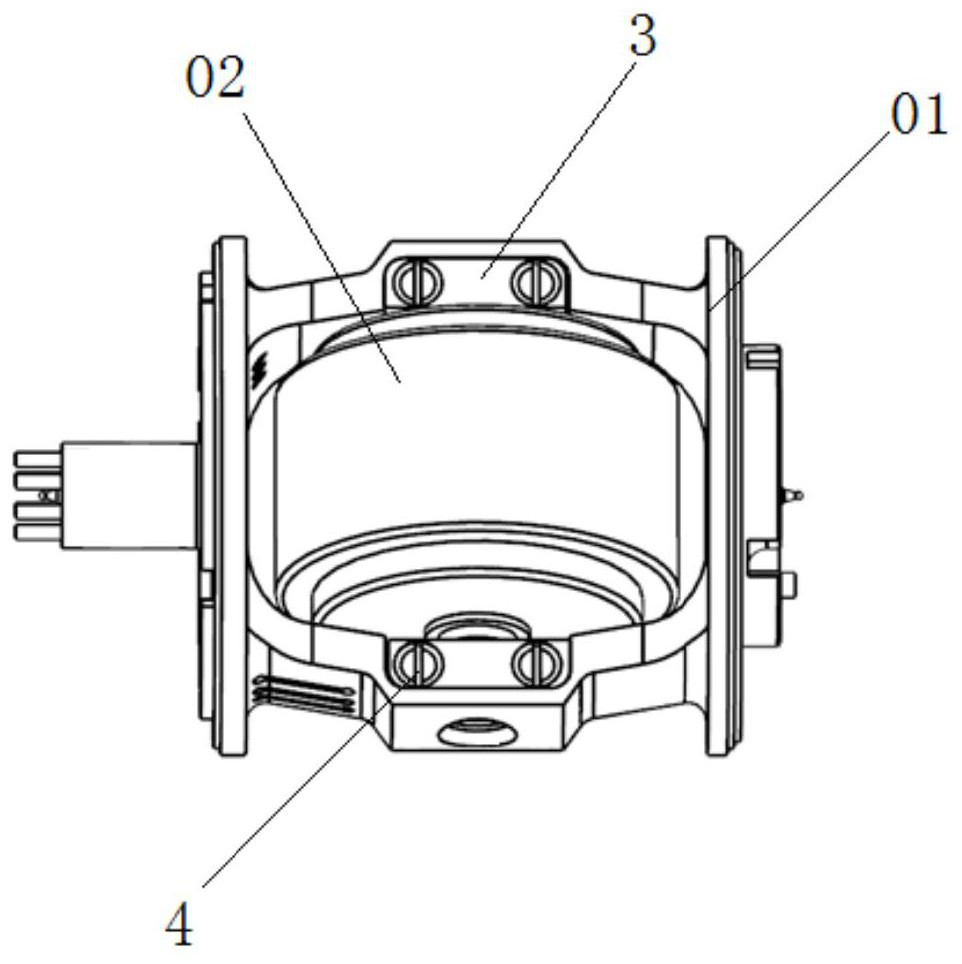
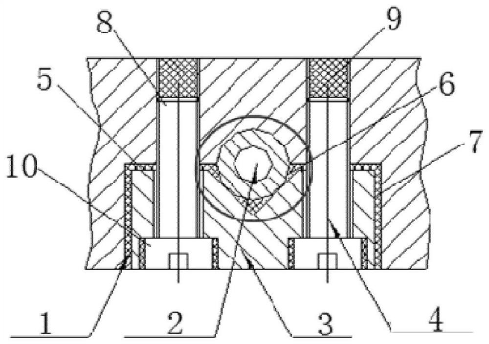
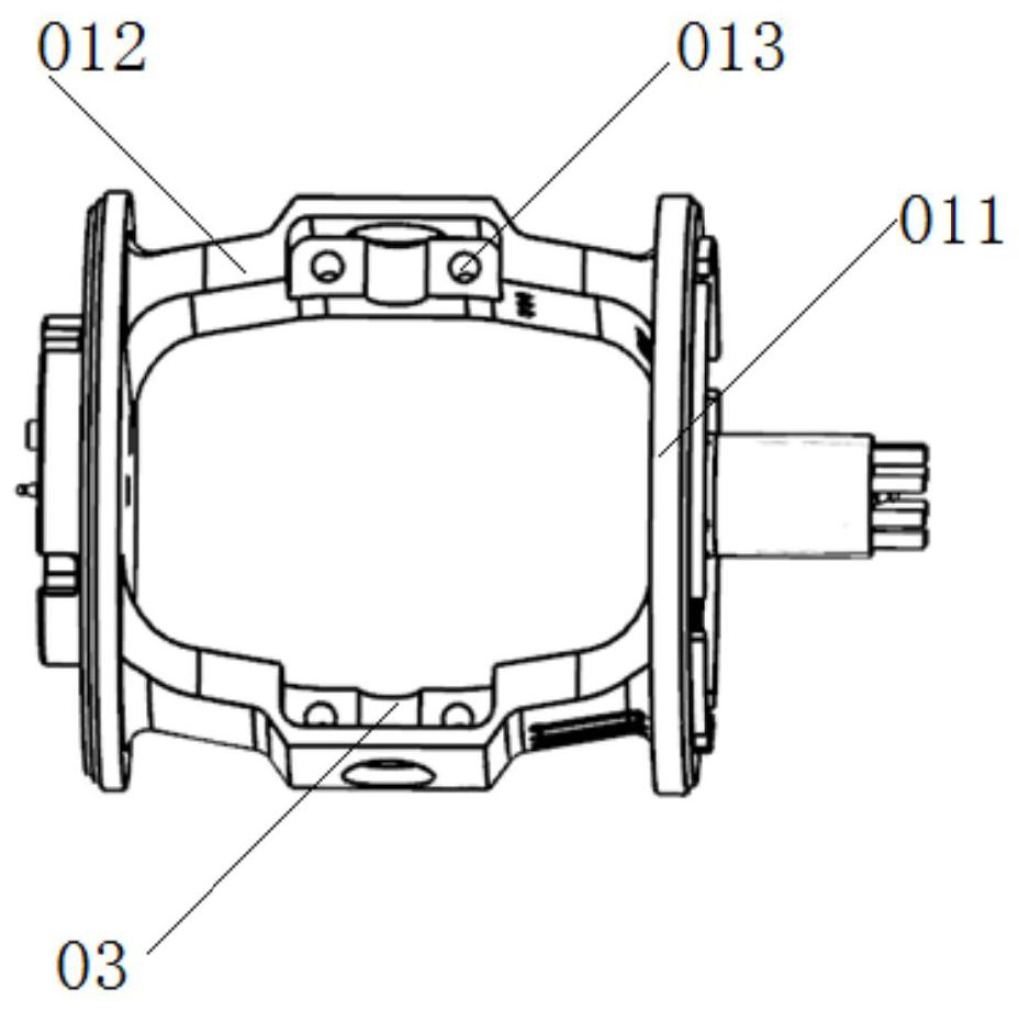
technical field [0001] The invention belongs to the technical field of gyroscope assembly and adjustment, and in particular relates to an installation method of a dynamic pressure motor and a frame assembly. Background technique [0002] Due to its anti-vibration, impact resistance, high reliability, and long life, the two-floating gyroscope is widely used in navigation and attitude systems of spacecraft, satellites, space stations, missiles, and ships. It is a very important inertial sensor to measure the angular motion of the vehicle. [0003] The manufacturing process of the second floating gyro involves difficult precision machining and precision assembly technology. The residual stress generated by assembly stress and bonding stress will affect the stability of the gyro, which in turn will affect the accuracy of navigation and attitude systems. [0004] The float assembly is the key component of the second float gyroscope, which is composed of the frame assembly 01 and...

Claims


Application Information

Patent Timeline
Patent Type & Authority Applications(China)
IPC IPC(8): B05D1/26B05C11/10B25B27/14B25B11/02
CPCB05D1/26B05C11/1015B05C11/1007B25B27/14B25B11/02
Inventor 辛小波刘智峰王玉琢王建青何超吴蕊郭清王悦
Owner XIAN AEROSPACE PRECISION ELECTROMECHANICAL INST
Learn More