Drilling device for road and bridge engineering

A drilling device and engineering technology, applied in positioning devices, driving devices, boring/drilling, etc., can solve the problems of wire sheath cutting circuit, accumulation of metal drilling chips, hidden safety hazards, etc., to achieve simple structure and improve utilization High efficiency, high safety effect

Active Publication Date: 2022-03-15
晟民建设有限公司
View PDF7 Cites 0 Cited by
  • Summary
  • Abstract
  • Description
  • Claims
  • Application Information

AI Technical Summary

Problems solved by technology

[0002] In road and bridge engineering, the drill bit is often used to drill through holes on the wiring square pipe with double wall surface and the inner side is used for wiring. During the drilling process, the metal drilling chips generated by drilling on the wiring square pipe cannot fall into the wiring square. Otherwise, the metal drilling chips falling into the wiring square tube will cut the outer skin of the internally arranged wires and cause a short circuit, which has a greater safety hazard
[0003] At present, when the drill bit drills the wiring square pipe, the metal cuttings produced by the upper wall of the wiring square pipe can be blown away by the supporting equipment, but the drill bit has been drilled from the upper wall of the wiring square pipe. The drilled holes go deep and continue to drill the lower wall of the wiring square pipe, which will cause the metal drilling chips generated when the lower wall of the wiring square pipe is drilled by the drill bit to accumulate in the wiring square pipe, and the metal chips arranged in the wiring square pipe The sheath of the wire will be scratched by the metal drilling chips accumulated in the wiring square tube due to its movement in the wiring square tube, which has a large safety hazard
[0004] The present invention designs a drilling device for road and bridge engineering to solve the problem of metal drilling chips accumulating inside the wiring square pipe due to drilling

Method used


Image

  • Drilling device for road and bridge engineering
  • Drilling device for road and bridge engineering
  • Drilling device for road and bridge engineering

Examples


Embodiment Construction

[0035] The accompanying drawings are all schematic diagrams of the implementation of the present invention, so as to understand the principle of structural operation. The specific product structure and proportional size can be determined according to the use environment and conventional technology.

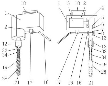
[0036] Such as figure 1 Shown, it comprises driving mechanism 1, drilling mechanism 19, wherein as figure 1 As shown, the drilling mechanism 19 installed on the driving mechanism 1 and driven by the driving mechanism 1 performs through-hole drilling on the upper and lower wall surfaces of the wiring square pipe 57 without chipping.

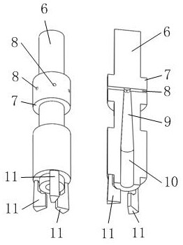
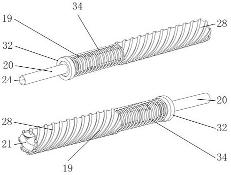
[0037] Such as image 3 , 4 As shown, the drilling mechanism 19 includes a round rod 20, a drill bit A21, a drill bit B28, an annulus A29, a block 30, a spring A34, an annulus D44, and a spring B53, wherein as Figure 4 , 6 , 9, the end of the round rod 20 has a twist drill bit A21 with a core thickness equal to the diameter of the round rod 20, an...


PUM


Abstract

The invention belongs to the field of road and bridge engineering drilling, and particularly relates to a drilling device for road and bridge engineering, which comprises a driving mechanism and a drilling mechanism, and the drilling mechanism mounted on the driving mechanism and driven by the driving mechanism is used for drilling through holes without chip falling on the upper and lower wall surfaces of a wiring square tube; a drill bit A and a cylindrical drill bit B are matched with each other to drill through holes in the upper wall face and the lower wall face of a wiring square pipe, and in the process that the drill bit A drills the upper wall face and the lower wall face of the wiring square pipe, metal drilling cuttings generated on the upper wall face and the lower wall face of the wiring square pipe can be stored in the space between an annular protrusion B on a round rod and the drill bit A through a spiral groove of the auger drill bit A and sealed and stored by the cylindrical drill bit B; metal drilling cuttings generated when the wall face drill bit A drills holes in the wiring square pipe fall into the wiring square pipe and cut the outer skin of an electric wire arranged in the wiring square pipe to cause short circuit, so that the electric wire in the wiring square pipe is protected to a certain degree, and higher safety is achieved.

Description

technical field [0001] The invention belongs to the field of road and bridge engineering drilling, in particular to a drilling device for road and bridge engineering. Background technique [0002] In road and bridge engineering, the drill bit is often used to drill through holes on the wiring square pipe with double wall surface and the inner side is used for wiring. During the drilling process, the metal drilling chips generated by drilling on the wiring square pipe cannot fall into the wiring square. Otherwise, the metal drilling chips falling into the wiring square tube will cut the outer skin of the internally arranged wires and cause a short circuit, which has a greater safety hazard. [0003] At present, when the drill bit drills the wiring square pipe, the metal cuttings produced by the upper wall of the wiring square pipe can be blown away by the supporting equipment, but the drill bit has been drilled from the upper wall of the wiring square pipe. The drilled holes...

Claims


Application Information

Patent Timeline
Patent Type & Authority Applications(China)
IPC IPC(8): B23B41/00B23B47/06B23B51/00B23Q3/00B23Q11/10
CPCB23B41/00B23B51/00B23Q3/00B23Q5/10B23Q11/10
Inventor 马钢锋罗秀平吴军鑫廖志刚施杏贞
Owner 晟民建设有限公司
Why Eureka
Try Eureka