Automatic screwdriver with adjustable operation station
A pneumatic screwdriver, adjustable technology, used in screwdrivers, power tools, manufacturing tools and other directions, can solve problems such as difficulty in manual operation
- Summary
- Abstract
- Description
- Claims
- Application Information
AI Technical Summary
Problems solved by technology
Method used
Image

Examples
Embodiment 1
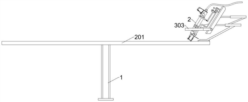
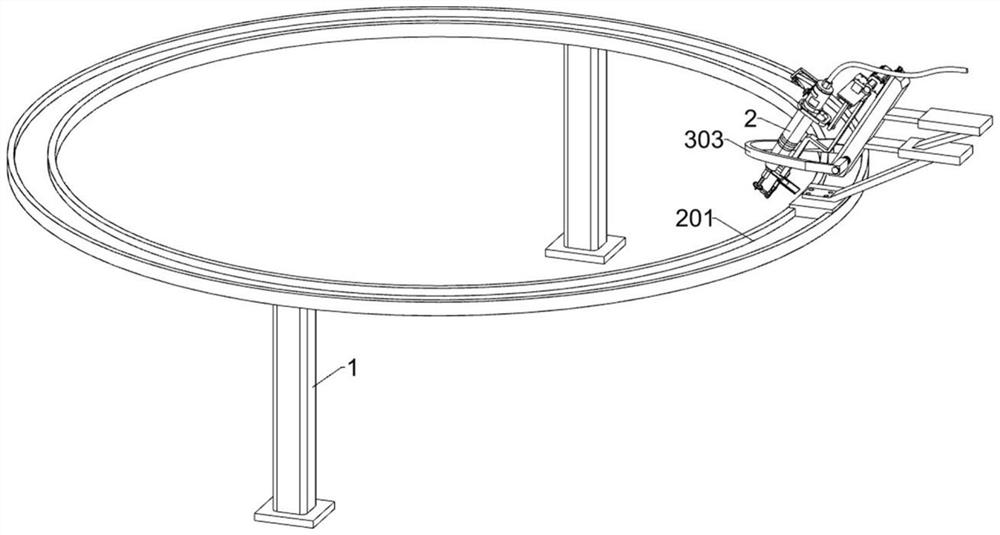
[0031] An operational station adjustable automatic screwdriver, such as Figure 1-8 As shown, including a fixed base 1, a pneumatic screwdriver 2, an angle adjustment assembly, an obstacle avoidance assembly; the fixed base 1 is provided with two, and the upper surface of the two fixed base 1 is mounted an angle adjustment assembly; angle adjustment component right side There is a pneumatic screwdriver 2; an obstacle avoidance assembly is installed on the right side of the angle adjustment assembly, and the barrier avoidance assembly is located outside the pneumatic screwdriver 2.
[0032] The angle adjustment assembly includes a first slip rail 201, a first driving member 202, a first connecting plate 203, a first elastic member 204, a second connecting plate 205, a second elastic member 206, mounting plate 207, a second sliding rail 208 , The second drive member 209, the first electric rotary shaft 2010, the first T-plate 2011, the second T-plate 2012, the third slide rail 2013, ...
Embodiment 2
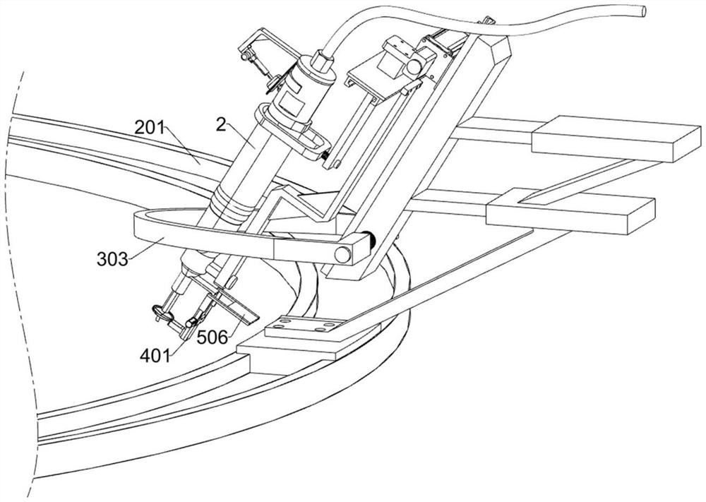
[0042] On the basis of Example 1, if figure 1 , Figure 9-10 The cleaning assembly is further included, and the lower side of the pneumatic screwdriver 2 is mounted, and the cleaning assembly includes a third L-shaped plate 401, a fourth slide rail 402, a fifth drive member 403, a collection frame 404, a ring block 405, The cleaning device 406 and the limit panel 407; the lower side of the pneumatic screwdriver 2 is fixed to the third L-shaped plate 401; the third L-shaped plate 401 is welded with the fourth slide rail 402; the fourth slide rail 402 slides A fifth drive member 403 is connected; the left side surface of the fifth drive member 403 is welded to collect box 404; the left side of the collecting frame 404 has a ring block 405; the inner side of the annular block 405 is provided with an annular array of cleanup 406; The lower side of the block 405 is welded to two front and rear symmetrical limit panels 407.
[0043] The ring block 405 has an gap corresponding to the posi...
Embodiment 3
[0047] On the basis of Example 2, if figure 1 , Figure 11-12 As shown, a silicid wire processing assembly is also included, and a silicone processing assembly is mounted on the right side of the third L-shaped plate 401, and the wire processing assembly includes a fourth L-shaped plate 501, a second electric rotary shaft 502, a transmission shaft 503, and the first Three elastic parts 504, fourth connecting plate 505 and auxiliary device 506; the third L-shaped plate 401 is connected to the fourth L-shaped plate 501; the middle of the third L-plate 401 is rotated connected to the drive shaft 503; fourth The second electric rotary shaft 502 is mounted on the front side of the L-shaped plate 501; the second electric rotary shaft 502 outputs two third elastic members 504, the exterior surface of the drive shaft 503; two third elastic parts 504 The upper end faces are fixed with a fourth connecting plate 505; the two fourth connecting plates 505 are mounted with auxiliary device 506. ...
PUM
 Abstract
Description
Claims
Application Information