Sliding block anti-falling locking device of press machine

A locking device and press technology, which is applied in the field of presses, can solve the problems of inconvenient maintenance and repair of presses or inconvenient mold repairs on the press, damage to sliders and related parts, and large falling amount of sliders, so as to achieve flexible and smooth coordination and shortening. Action time, the effect of reducing collision

Pending Publication Date: 2022-03-15
CHINFONG CHINA MECHANICAL IND LIMITED
View PDF0 Cites 1 Cited by
  • Summary
  • Abstract
  • Description
  • Claims
  • Application Information

AI Technical Summary

Problems solved by technology

But this anti-drop device has the following defects in actual use: 1, the locking position of the device has limitations and cannot be selected, and usually all locks when the slide block is at the position of the upper dead center, thereby giving the press It is inconvenient for maintenance and repair or mold repair on the machine; 2. The pin hole on the limit block is a waist-shaped hole to adapt to different mold closing heights. When locking, the pin is inserted into the waist-shaped hole of the limit block. The gap between the holes changes with the closing height of the mold. The larger the gap, the greater the drop of the slider, which poses a safety hazard; 3. There is no buffer in the anti-drop device, and once the slider falls, there will be a large impact load. There is damage to the slider and associated parts; 4. The feedback on the pin position is generally obtained through the indirect feedback of the magnetic detection of the cylinder piston position, and there are certain false detections

Method used


Image

  • Sliding block anti-falling locking device of press machine
  • Sliding block anti-falling locking device of press machine
  • Sliding block anti-falling locking device of press machine

Examples


Embodiment Construction

[0023] The present invention will be further described in detail below in conjunction with the accompanying drawings and embodiments.

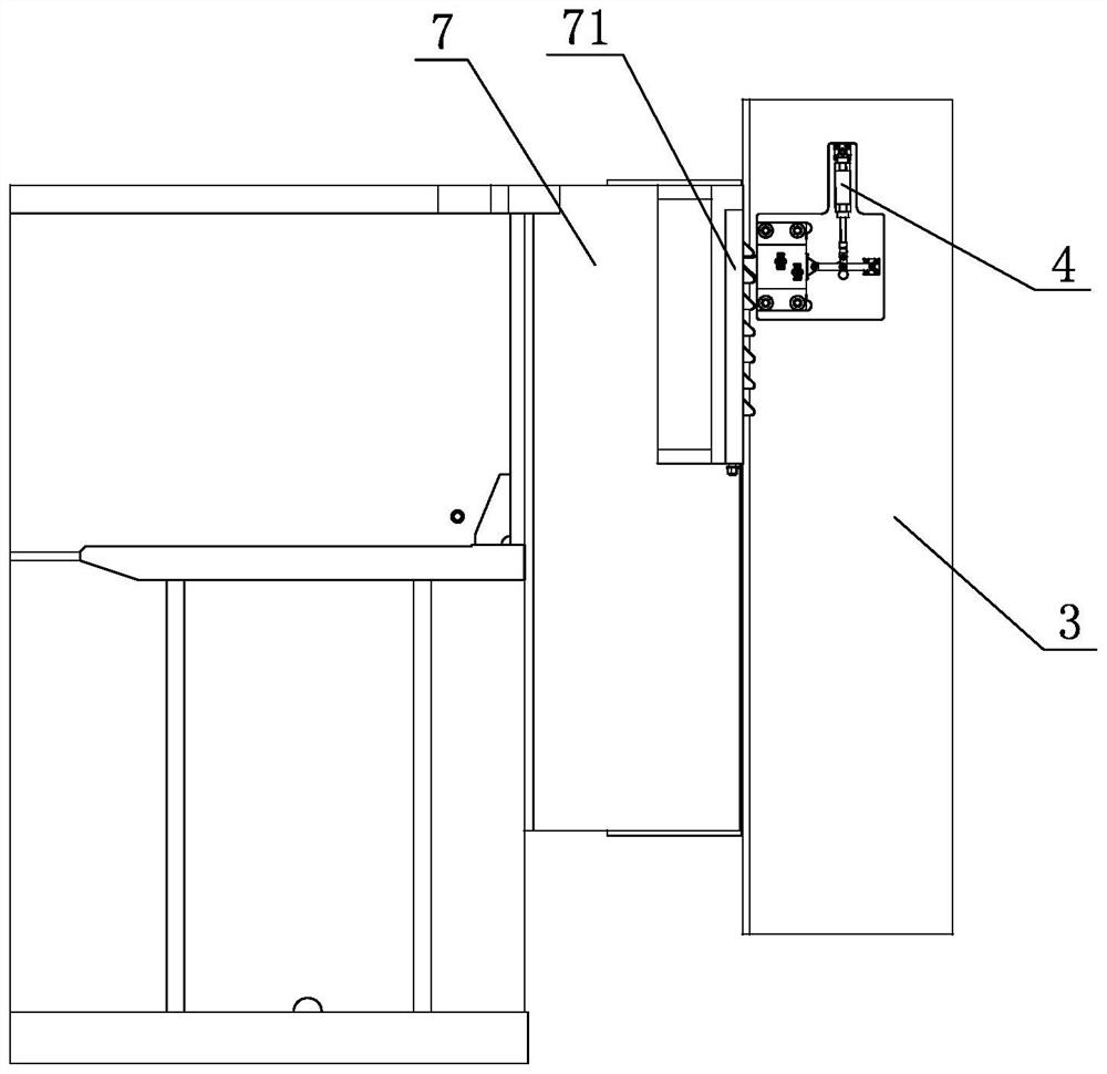
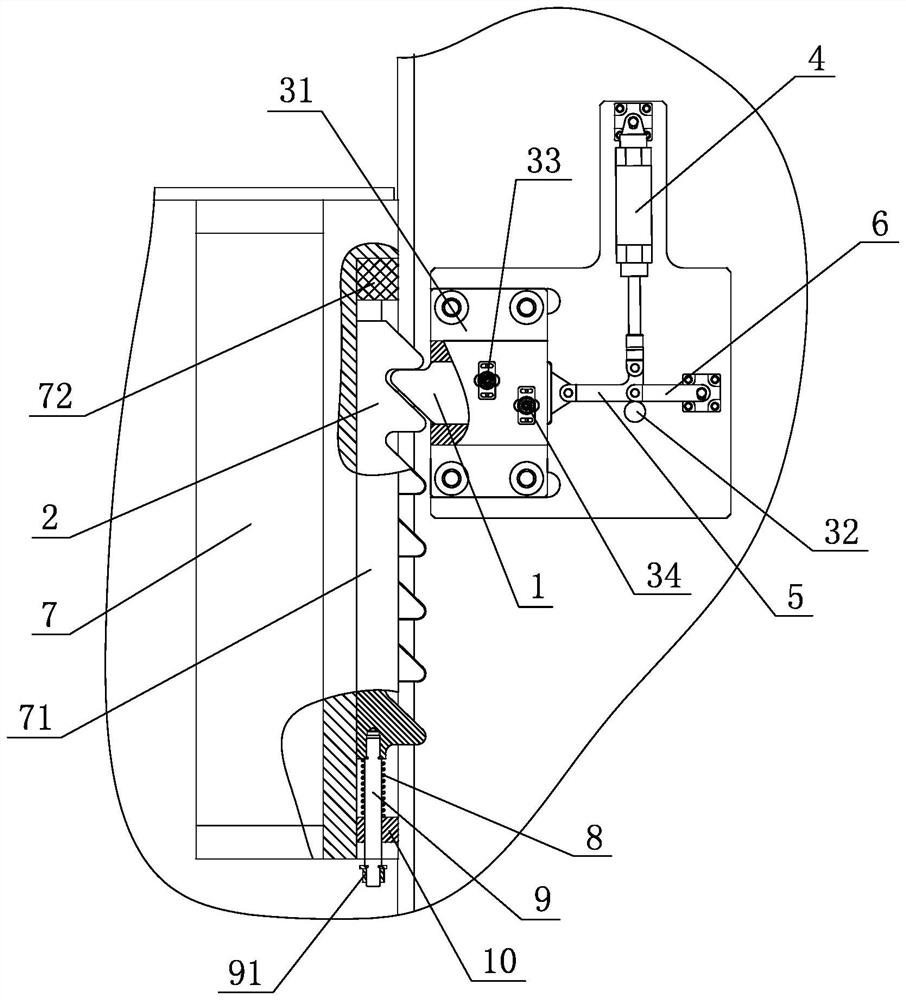
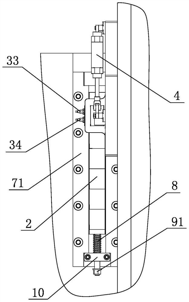
[0024] As shown in the figure, a sliding block anti-drop locking device of a press includes a lock tongue 1 and a rack 2, the lock tongue is arranged on the frame column 3 of the press machine, and the frame column 3 is provided with a lock tongue driving mechanism and the deadbolt position detection mechanism, the deadbolt driving mechanism includes a cylinder 4, an L-shaped connecting rod 5 and a straight connecting rod 6, the cylinder 4 is fixed on the frame column 3, and one end of the L-shaped connecting rod 5 is connected to the piston rod of the cylinder 4 The ends are hinged, the other end of the L-shaped connecting rod 5 is hinged with the rear end of the dead bolt 1, one end of the straight connecting rod 6 is hinged with the turning point of the L-shaped connecting rod 5, and the other end of the straight connecting rod 6 is connecte...


PUM


Abstract

The sliding block anti-falling locking device of the press machine is characterized by comprising a spring bolt and a rack, the spring bolt is arranged on a machine frame stand column of the press machine, a spring bolt driving mechanism and a spring bolt position detecting mechanism are arranged on the machine frame stand column, and the rack is arranged on the side face of a sliding block and is in up-down sliding fit with the sliding block; a rack elastic supporting mechanism is arranged on the sliding block, and when the spring bolt driving mechanism drives the spring bolt to be inserted into the rack, the sliding block is locked; the anti-falling locking device has the advantages that anti-falling locking is carried out on the sliding block through matching of the spring bolt and the rack, when the sliding block stops at different height positions, the sliding block can be locked by the locking device so as to play a role in safety, and the sliding block does not need to be limited to the upper dead point position of the sliding block; and the length of the rack is changed to adapt to different stroke lengths and die height adjusting quantities of the press machine.

Description

technical field [0001] The invention relates to a press, in particular to a sliding block anti-drop locking device of the press. Background technique [0002] The existing presses are all equipped with a safety device to prevent the slide block from accidentally falling when it stops, and the safety device basically adopts the cylinder pin type slide block fall prevention device at present, and the specific structure is: fixed on the frame A cylinder is provided, the piston rod of the cylinder is fixedly connected with a bolt, and a limit block is fixedly arranged on the slider, and the action of the cylinder drives the bolt to insert or move out of the pin hole of the limit block to lock or unlock the slider. But this anti-drop device has the following defects in actual use: 1, the locking position of the device has limitations and cannot be selected, and usually all locks when the slide block is at the position of the upper dead center, thereby giving the press It is inco...

Claims


Application Information

Patent Timeline
Patent Type & Authority Applications(China)
IPC IPC(8): B30B15/28B30B15/00
CPCB30B15/28B30B15/00B30B15/0076
Inventor 潘祺钦李娜王菡杰包松东张文
Owner CHINFONG CHINA MECHANICAL IND LIMITED
Why Eureka
Try Eureka