Integrated slurry treatment system

A treatment system and integrated technology, applied in sludge treatment, water/sludge/sewage treatment, chemical instruments and methods, etc., can solve the problems of restricted pipeline transportation, troublesome pipeline installation, difficult to separate, etc., and achieve simplification Difficulty, efficiency improvement, waste reduction effects

Pending Publication Date: 2022-03-15
三川德青工程机械有限公司
View PDF5 Cites 0 Cited by
  • Summary
  • Abstract
  • Description
  • Claims
  • Application Information

AI Technical Summary

Problems solved by technology

However, there are as many as 19 frames in this scheme, and it is very troublesome to install and assemble on site
In particular, the installation of pipelines is very troublesome, and the structure of the frame also limits the transportation of components such as pipelines
Furthermore, the existing shield engineering usually uses mud to participate in the shield construction to achieve the effect of lubrication, cooling and wall protection. It is necessary to prepare the mud containing bentonite on site, which is not only difficult to separate after use, but also wastes a lot

Method used


Image

  • Integrated slurry treatment system
  • Integrated slurry treatment system
  • Integrated slurry treatment system

Examples


Embodiment 1

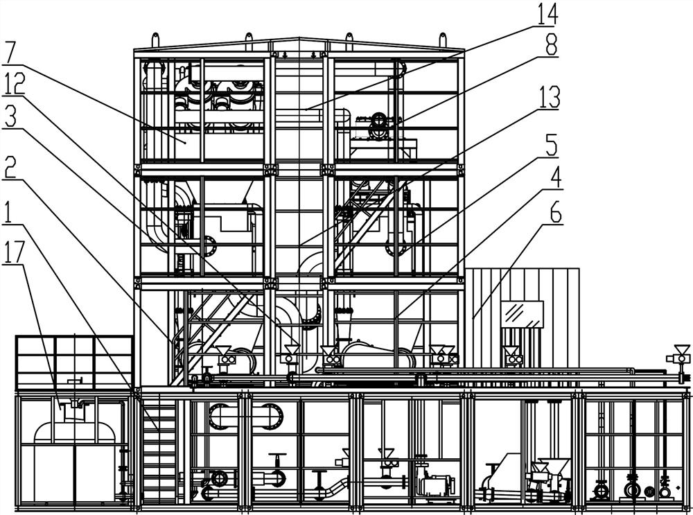
[0035] Such as Figure 1~3 Among them, an integrated mud treatment system, which includes a mud box assembly 1, and a secondary slurry storage tank frame assembly 2 and a primary slurry storage tank frame assembly 4 are arranged above the mud box assembly 1;

[0036] A dewatering screen frame assembly 3 is provided on the frame assembly 2 of the secondary slurry storage tank, and a pre-screen frame assembly 5 is provided on the frame assembly 4 of the primary slurry storage tank;

[0037] A cyclone frame assembly 7 is arranged on the frame assembly 2 of the secondary slurry storage tank, and a pre-screening slurry inlet frame assembly 8 is arranged on the pre-screening frame assembly 5 . With this structure, the pipeline structure can be simplified, thereby reducing the number of frame assemblies.

[0038] The preferred solution is as figure 1 , 3 Among them, the secondary slurry storage tank frame assembly 2 and the primary slurry storage tank frame assembly 4 are located ...

Embodiment 2

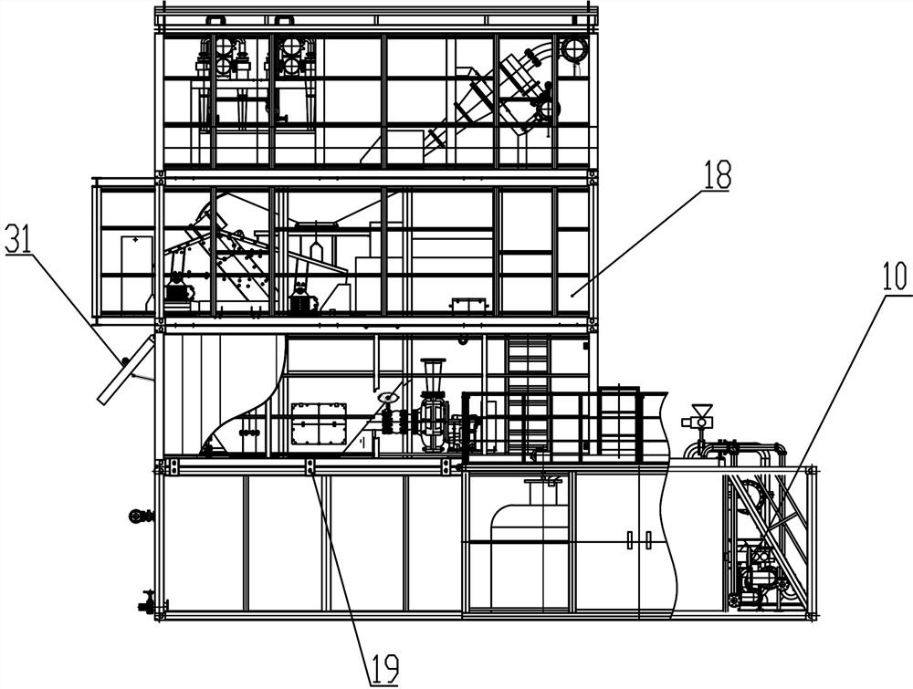
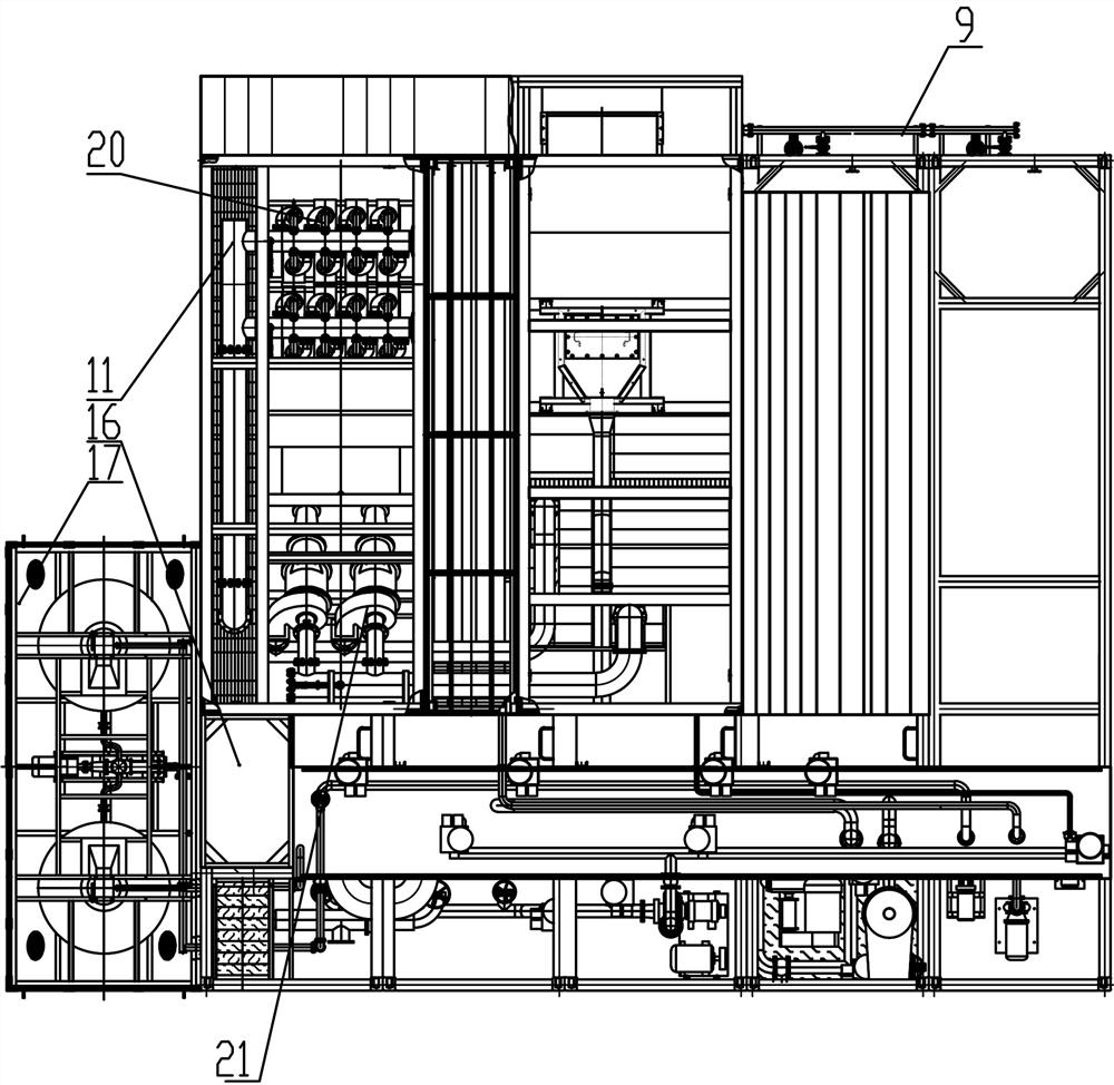
[0057] The preferred solution is as figure 1 , 3 , 5, also be provided with circulation pulping system 17, circulation pulping system 17 is provided with new pulp box 25, clean water box 26, waste pulp box 27 and pulp mixing box 28, feed hopper 30 is mixed with new pulp by shearing pump The box 25 is connected, and the incoming new mud is evenly mixed under the action of the shear pump. The overflow port of the secondary slurry storage tank and the primary slurry storage tank is connected with the slurry mixing box 28, and a valve is provided on the connected pipeline. For switching the mud from different slurry storage tanks according to the liquid levels of the slurry distribution box 28, the secondary slurry storage tank and the primary slurry storage tank, see image 3 . The new slurry box 25 is connected with the slurry matching box 28, and is used to mix new slurry in the recovered slurry, so that the clear water box 26 is connected with the new slurry box 25, the wast...


PUM


Abstract

The invention provides an integrated slurry treatment system which comprises a slurry box assembly, and a second-stage slurry storage tank frame assembly and a first-stage slurry storage tank frame assembly are arranged above the slurry box assembly. A dewatering screen frame assembly is arranged on the second-stage slurry storage tank frame assembly, and a pre-screening frame assembly is arranged on the first-stage slurry storage tank frame assembly; a cyclone frame assembly is arranged on the secondary slurry storage tank frame assembly, and a pre-screening slurry inlet frame assembly is arranged on the pre-screening frame assembly. By adopting the scheme, the difficulty of field installation can be greatly simplified, the slurry separation treatment efficiency is improved, the slurry can be recycled, and the waste of the slurry in the construction process is reduced.

Description

technical field [0001] The invention relates to the field of steel truss precast plate preparation, in particular to an integrated mud treatment system. Background technique [0002] In the shield tunneling project, a large amount of sludge will be generated during construction, which needs to be separated and treated. The separated clean water can be recycled, and the concentrated mud can be transported or prepared into building materials. The existing mud-water separation equipment occupies a large area, consumes a large amount of materials, and consumes a lot of energy, which is not conducive to mobile loading and unloading, and the applicable working conditions are not flexible enough. Chinese patent document CN103752074A records a three-dimensional space integrated mud purification system, which adopts a combination of multiple standard-sized functional frames to save floor space. But there are as many as 19 frames in this scheme, and it is very troublesome to install ...

Claims


Application Information

Patent Timeline
Patent Type & Authority Applications(China)
IPC IPC(8): C02F11/121C02F11/127
CPCC02F11/121C02F11/127
Inventor 甘虎陈娟陈睿陶鹏朱友文盖佰奇
Owner 三川德青工程机械有限公司
Why Eureka
Try Eureka