Intelligent centrifugal device applied to laboratory and work method of intelligent centrifugal device

A centrifugal device and intelligent technology, applied to centrifuges with rotating drums, centrifuges, etc., can solve the problems of inability to display working status, inconvenient control and use of centrifuge operations, single centrifuge materials and products, and achieve improvement Scope of application, easy management and control, and time-saving effect

Inactive Publication Date: 2016-05-04
TAICANG WEIGUAN ELECTROMECHANICAL
View PDF7 Cites 0 Cited by
  • Summary
  • Abstract
  • Description
  • Claims
  • Application Information

AI Technical Summary

Problems solved by technology

[0003] In the actual use process, the existing structure of the laboratory centrifuge has a complex structure and is inconvenient to control and use the centrifuge operation; At the same time, the working efficiency of centrifugation is low, the effect is poor, and it is impossible to realize the display of the working status and the prompt after centrifugation is completed, and it is also impossible to realize remote control. In order to improve the efficiency of centrifugation and the convenience of work, this is an urgent problem to be solved at present.

Method used


Image

  • Intelligent centrifugal device applied to laboratory and work method of intelligent centrifugal device
  • Intelligent centrifugal device applied to laboratory and work method of intelligent centrifugal device

Examples


Embodiment

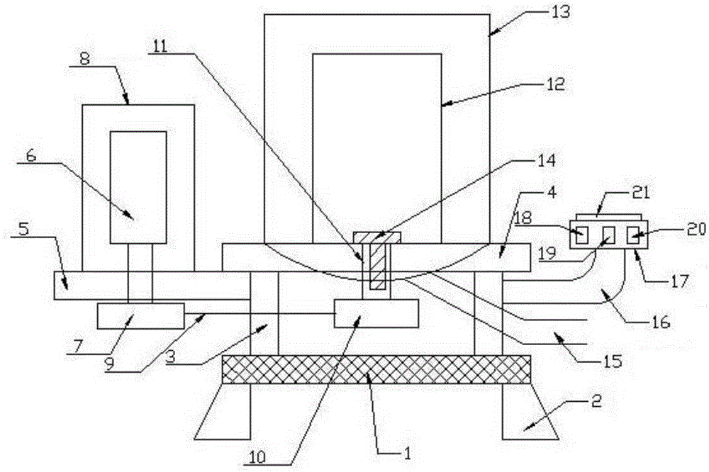
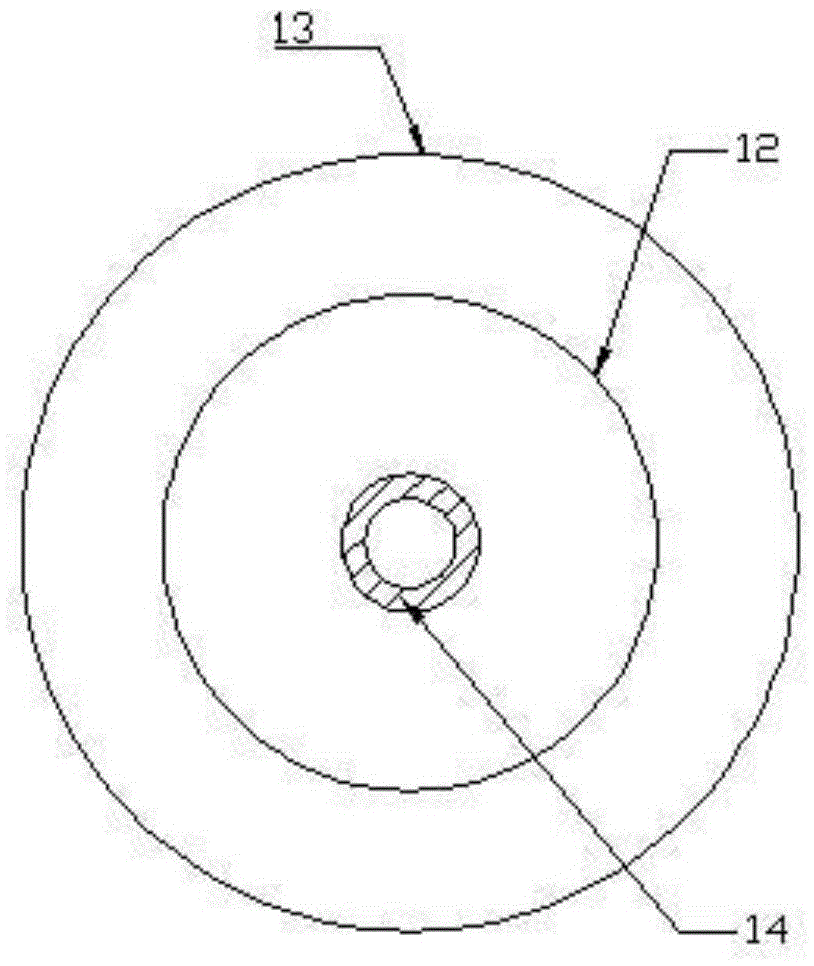
[0017] Such as figure 1 and figure 2 A kind of intelligent centrifugation device applied to the laboratory is shown, which consists of a base 1, a leg 2 arranged at the bottom of the base 1, a support frame 3 arranged on the base 1, and a centrifuge set on one side of the support frame 3. The driving assembly is composed of a centrifugal filter assembly arranged on the support frame 3, and a control assembly arranged on the other side of the support frame 3; the centrifugal drive assembly includes a motor mounting plate 5 arranged on the support frame 3, and is arranged on the motor The driving motor 6 on the mounting plate 5, and the transmission wheel 7 that is arranged on the motor mounting plate 5 below and is connected with the driving motor 6; the centrifugal filter assembly includes the mounting seat 4 that is arranged on the support frame 3, and is arranged on the mounting seat 4. The inner centrifuge tank 12 at the middle upper part, and the outer centrifuge tank 13...


PUM


Abstract

The invention belongs to the technical field of centrifugal machine application, and particularly discloses an intelligent centrifugal device applied to a laboratory. The intelligent centrifugal device is composed of a base, landing legs, a supporting frame, a centrifugal drive assembly, a centrifugal filtering assembly and a control assembly, wherein the landing legs are arranged at the bottom of the base, the supporting frame is arranged on the base, the centrifugal drive assembly is arranged on one side of the supporting frame, the centrifugal filtering assembly is arranged on the supporting frame, and the control assembly is arranged on the other side of the supporting frame. The split type design is adopted in the drive assembly and the centrifugal filtering assembly, control is facilitated, the separation treatment efficiency is high, time is saved, and work efficiency is improved. A detachable structure is adopted among a positioning pin shaft, an inner centrifugal tank and a transmission shaft, so that cleaning is facilitated, inner centrifugal tanks of different structures can be conveniently replaced according to different materials, and the application range of the integral structure is enlarged. The control assembly can display the work state of a drive motor in real time, so that control of an experimenter is facilitated, meanwhile, control can be carried out through a remote upper computer, and the work efficiency is improved.

Description

technical field [0001] The invention belongs to the technical field of centrifuge application, and in particular relates to an intelligent centrifugal device applied in a laboratory and a working method thereof, which can effectively improve the scope of application of the centrifuge and the centrifugal processing efficiency of materials. Background technique [0002] A centrifuge is a machine that uses centrifugal force to separate components in a mixture of liquid and solid particles or liquid and liquid. The centrifuge is mainly used to separate the solid particles in the suspension from the liquid, or to separate the two densities in the emulsion. Separate different, immiscible liquids (such as separating cream from milk); it can also be used to remove liquid from wet solids, such as drying wet clothes with a washing machine; special ultra-speed tube separators can also separate different Density gas mixture; using the characteristics of different sedimentation speeds of...

Claims


Application Information

Patent Timeline
Patent Type & Authority Applications(China)
IPC IPC(8): B04B1/00B04B7/08B04B9/08B04B13/00
CPCB04B1/00B04B7/08B04B9/08B04B13/00
Inventor 林兰英
Owner TAICANG WEIGUAN ELECTROMECHANICAL
Why Eureka
Try Eureka