Tin dross separating and reclaiming device

A technology for separation and recovery of tin slag, applied in the direction of improving process efficiency, can solve the problems of troublesome operation, production waste, large volume, etc., and achieve the effect of simple structure, high efficiency and small volume

Inactive Publication Date: 2011-06-01
SHENZHEN SKYWORTH RGB ELECTRONICS CO LTD
View PDF0 Cites 0 Cited by
  • Summary
  • Abstract
  • Description
  • Claims
  • Application Information

AI Technical Summary

Problems solved by technology

[0002] In the process of using a wave soldering machine to solder circuit board components, the soldering machine will oxidize part of the liquid solder that is in contact with the air during high-temperature operation, and produce the so-called "tin slag" substance, the main component of which is tin slag It is metal oxides such as tin and some residual flux and its oxides. The accumulation of tin slag in the tin furnace of the soldering machine will affect the soldering quality of the circuit board. The above tin slag is salvaged and cleaned, but this salvage process cannot simply clean up tin slag and other useless substances. The salvaged substances often contain some still usable pure metal solder. If all of them are treated as waste tin slag It will bring a lot of waste to the actual production, so it is necessary to treat the tin slag and separate the pure solder entrained in the tin slag
The traditional way to deal with tin slag is to collect it first and hand it over to the solder manufacturer for remelting or other chemical reactions for purification. This method actually requires the production unit to sell this part of the tin slag as waste, which directly causes production waste.
In addition, there are currently "slag reduction processing machines", the principle of which is also a purely physical method of heating, melting and separating the tin slag to extract the metal solder entrained in it and recycle it to the wave soldering machine. This kind of machine is expensive and bulky, and cannot be directly applied on the production line. It needs to collect all the tin slag and then process it uniformly. The operation is extremely troublesome.

Method used


Image

  • Tin dross separating and reclaiming device
  • Tin dross separating and reclaiming device

Examples


Embodiment Construction

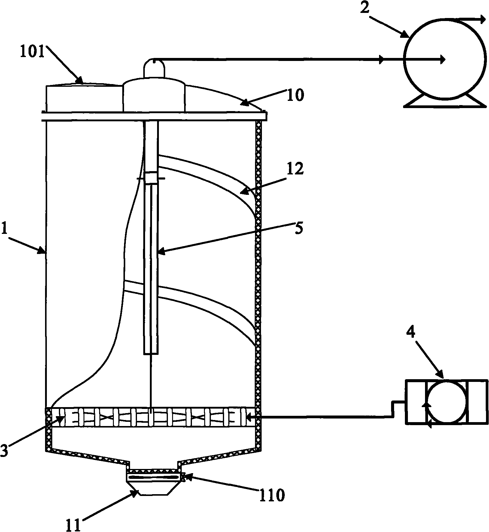
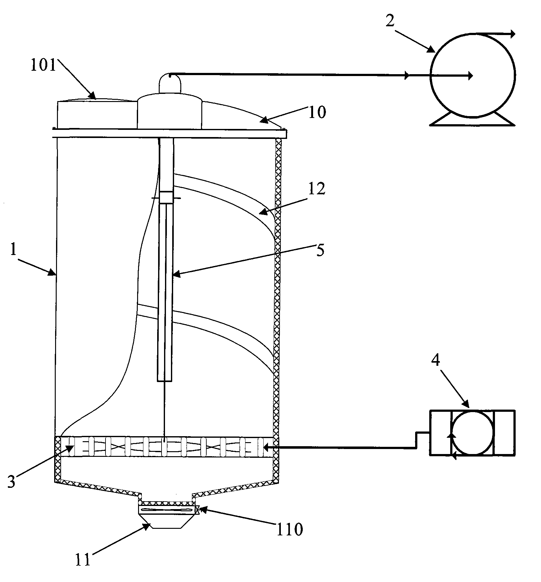
[0008] see figure 1 As shown, a tin slag separation and recovery device of the present invention includes a tin slag container 1 for containing tin slag, a vacuum pump system 2 installed on the top of the tin slag container 1, and an electric heating device installed at the bottom of the tin slag container 1 Control System. Wherein, the tin slag container 1 is a steel metal can-shaped container, and the top of the main body of the tin slag container 1 is provided with a top cover 10, and the top cover 10 is connected with the main body of the tin slag container 1 by screws. The top cover 10 is partially provided with a feed port 101 with a locking cover, and the tin slag to be separated is poured into the tin slag container 1 from the feed port 101 . The lower part of the main body of the tin slag container 1 is provided with a discharge port 11 with a valve 110 , and the metal solder and tin ash after separation of the tin slag are discharged from the discharge port 11 . Th...


PUM


Abstract

The invention discloses a tin dross separating and reclaiming device. The device comprises a tin dross tank for accommodating the tin dross, a vacuum pump system which is arranged on the top of the tin dross tank, and an electric heating control system which is arranged on the bottom of the tin dross tank, wherein a spiral gathering sill is arranged on the inner wall of the tin dross tank; and a vibration rod system is arranged in the axes position of the tin dross tank. The tin dross separating and reclaiming device perform treatment in a vacuum state through the vacuum pump system, and adopts a mode of vibration and the spiral gathering sill to stir materials, thereby ensuring that the whole process of heating and melting has better effect, higher speed, high efficiency of separation treatment, simple structure and small volume, and can be directly applied to operation on a production line.

Description

【Technical field】 [0001] The invention relates to the technical field of processing tin slag produced by a soldering machine on a production line, in particular to a tin slag separation and recovery device. 【Background technique】 [0002] In the process of using a wave soldering machine to solder circuit board components, the soldering machine will oxidize part of the liquid solder that is in contact with the air during high-temperature operation, and produce the so-called "tin slag" substance, the main component of which is tin slag It is metal oxides such as tin and some residual flux and its oxides. The accumulation of tin slag in the tin furnace of the soldering machine will affect the soldering quality of the circuit board. The above tin slag is salvaged and cleaned, but this salvage process cannot simply clean up tin slag and other useless substances. The salvaged substances often contain some still usable pure metal solder. If all of them are treated as waste tin slag...

Claims


Application Information

Patent Timeline
Patent Type & Authority Patents(China)
IPC IPC(8): C22B25/06C22B7/04
CPCY02P10/20
Inventor 甄幸文
Owner SHENZHEN SKYWORTH RGB ELECTRONICS CO LTD
Why Eureka
Try Eureka