
Laser separation machining method and device for optical crystal

An optical crystal and laser technology, used in metal processing equipment, laser welding equipment, manufacturing tools, etc., can solve the problems of increasing the difficulty of optical crystal processing, changing the optical performance of optical crystals, and losing control of the separation processing direction, so as to improve the separation processing efficiency. , the separation processing mouth is steep, the effect of suppressing negative effects

Active Publication Date: 2014-11-12
武汉飞能达激光技术有限公司
View PDF8 Cites 0 Cited by
  • Summary
  • Abstract
  • Description
  • Claims
  • Application Information

AI Technical Summary

Problems solved by technology

However, the high-precision polishing and leveling of anisotropic, soft, brittle high-optical crystals is not only cumbersome, complicated, time-consuming and labor-intensive, but also easily breaks during the polishing and leveling process, and it needs to be done again after separation. Polishing undoubtedly increases the processing difficulty of optical crystals
[0006] 2. The slits produced by laser thermal separation processing of transparent optical crystals will change the refractive index of the optical crystals due to the entry of air, causing the transmission direction of the laser beam to change, not only dissipating the laser energy, causing the separation depth to become shallower and the refracted laser The energy is absorbed by the optical crystal and causes the optical crystal to burst, resulting in loss of control of the separation processing direction and destruction
[0007] 3. The heat generated during laser thermal separation and processing of transparent optical crystals will cause the temperature of the end surface material of the separation port to be too high, which will change the optical properties of the optical crystal, and will also lead to an increase in the roughness of the end surface

Method used


Image

  • Laser separation machining method and device for optical crystal
  • Laser separation machining method and device for optical crystal
  • Laser separation machining method and device for optical crystal

Examples


example 1

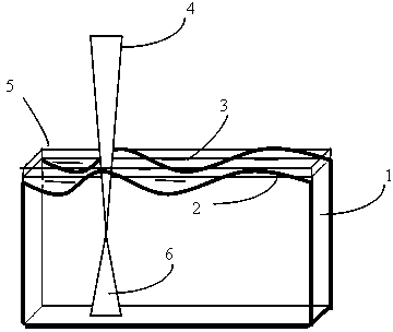
[0047] The present invention adopts an output wavelength of 1070nm, an output peak laser power of 50W, and a pulse energy of 1J as a fiber laser with a low peak power and a high-energy laser beam. The diameter of the focused spot is 50 μm, and the size of the separated and processed DKDP optical crystal sample is the length 60mm, thickness 12mm. Apply DKDP saturated optical crystal solution on the surface of DKDP optical crystal after simple rough grinding, polishing and wiping. The separation processing speed is 0.6m / min, the peak output power of the fiber laser is 50W, the pulse energy is 1J, and the scanning speed is 1m / min. Experimental results: The optical crystal is separated along the laser scanning line direction, without fragmentation, high separation precision, steep separation processing mouth, and smooth separation processing surface.

example 2

[0049] The present invention adopts a YLM-200 type optical brazing laser, the output wavelength is 1064nm, the output continuous laser power is 200W, and the diameter of the focused spot is 80μm respectively. Experimental method: Use KDP saturated optical crystal solution to coat on the surface of KDP optical crystal after simple rough grinding, polishing and wiping. The output power of the separated processed fiber laser is 175W, and the scanning speed is 1.8m / min. Experimental results: The optical crystal is separated along the direction of the laser scanning line, and the separation end face is relatively rough. It needs to be polished to obtain the optical plane required in the application.

example 3

[0051] The present invention adopts the Awave-532-20-25K type green laser, the output wavelength is 532nm, the output maximum single pulse energy is 40μJ, the focus spot diameter is 20μm respectively, and the lithium acid (LiNbO3-LN) optical crystal is separated, and the size is Length 98mm, thickness 10mm. Experimental method: Coat the saturated optical crystal solution of lithium-acid optical crystals on the surface of lithium-acid optical crystals after simple rough grinding, polishing and wiping, and the laser scanning speed is 1.3m / min. Scanning and separation processing along the direction of the coating liquid track, after separation, the processed end surface is relatively smooth, and there are no cracks in other directions inside the optical crystal. Simple mechanical smoothing and polishing are required to obtain the optical plane required in the application.

[0052] This method can also be used for laser separation and processing of other optical crystals by liquid...


PUM

PropertyMeasurementUnit
conversion efficiencyaaaaaaaaaa

Abstract

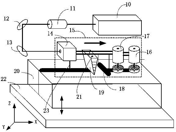
The invention discloses a laser separation machining method and a laser separation machining device for optical crystal. The method comprises the following steps of: simply roughly rubbing and polishing the convex-concave surface of the optical crystal along a laser separation machining locus, and cleaning a hydrolysis atomization layer and impurities on the surface to form a transparent locus of which the width is greater than the diameter of a laser incident light spot; uniformly coating a saturated solution of the same optical crystal material on the surface of the wiped optical crystal to fill the convex-concave part of the surface of the optical crystal; and performing scanning separation machining by adopting laser along the locus of the saturated solution of the optical crystal. The device comprises a laser machining system and a solution coating system; and a laser focusing device, a solution coating device, a wiping device, a polishing device and a polishing device are sequentially arranged on a linear moving mechanism along the X-axis direction. By the method and the device, a non-fragmented optical crystal sheet with high separation precision, abrupt separation machining port, smooth cut separation surface and high separation quality can be obtained, and negative effects caused by over high laser temperature can be effectively inhibited.

Description

technical field [0001] The invention belongs to the technical field of laser processing applications, and in particular relates to a method and device for laser separation and processing of transparent optical crystals. The method is especially suitable for optical crystal blanks that have not been professionally polished. Background technique [0002] Transparent optical crystals, such as phosphate KDP, DKDP, potassium titanyl phosphate (KTP), lithium triborate LiB3O5 (LBO), and LiNbO3 (LN), KNbO3 (KN), potassium dihydrogen phosphate (KDP), Crystals such as ammonium dihydrogen phosphate, BaTiO3 and Gd(MoO4)3 have long been considered as good electro-optic materials, and have been widely used in optoelectronic technology. They are important materials for frequency multipliers in high-power drivers and electro-optic devices. , has been widely used in nonlinear optics for frequency doubling, sum frequency, difference frequency and frequency mixing of light. In particular, KDP...

Claims


Application Information

Patent Timeline
Patent Type & Authority Patents(China)
IPC IPC(8): B23K26/38B23K26/064B23K26/60B23K26/70B23K26/402
Inventor 段军邓磊敏曾晓雁蒋明
Owner 武汉飞能达激光技术有限公司
Learn More