Gob-side entry retaining side goaf collecting device and method

A technology of collecting device and empty lane retention, which is applied in the directions of measuring devices and instruments, can solve the problems of easy damage of the collecting device and difficulty in monitoring, and achieves the effect of being convenient to carry.

Pending Publication Date: 2022-03-15
INNER MONGOLIA UNIV OF SCI & TECH
View PDF6 Cites 0 Cited by
  • Summary
  • Abstract
  • Description
  • Claims
  • Application Information

AI Technical Summary

Problems solved by technology

[0006] In order to solve technical problems such as easy damage to the collection device and difficult monitoring existing in the prior art, the present invention provides a goaf collection device and method at the side of gob-side entry retaining, which is pre-embedded in the support wall A num

Method used


Image

  • Gob-side entry retaining side goaf collecting device and method
  • Gob-side entry retaining side goaf collecting device and method
  • Gob-side entry retaining side goaf collecting device and method

Examples


Example Embodiment

[0040] Example one

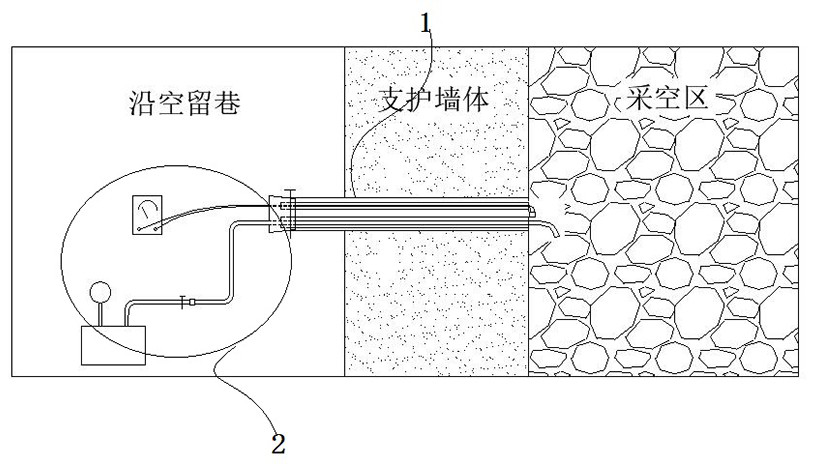
[0041] Such as figure 2 As shown, the valve body includes a seal and opening of the entire monitoring conduit 1 by the first valve body 3 along the empty lane side, and is closed by the first valve body 3; when the temperature collected and the gas collection is collected, Open the corresponding first valve body 3, in conjunction with the monitoring pipe 1; after standing for 10-20 minutes, the air and temperature measurement operation is performed; after the air intake, the temperature is measured, the acquisition unit 2 will be monitored. Remove, then quickly close the corresponding first valve body 3.

Example Embodiment

[0042] Example 2

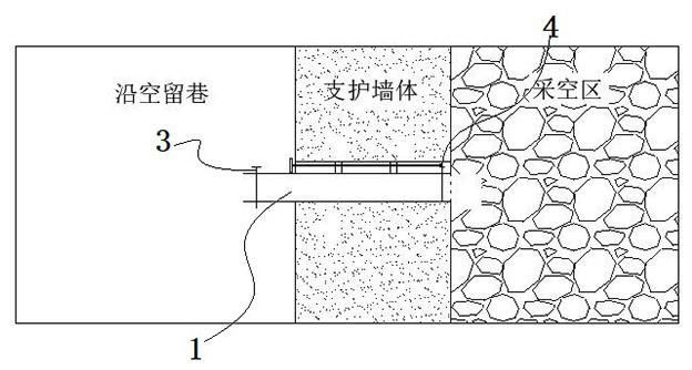
[0043] Such as figure 2 As shown, the valve body includes a second valve body 4 provided and a second valve body 4 provided on one side of the empty area, and the second valve body 4 is provided in a control assembly along the railway. Control is opened, closed; when the temperature acquisition is collected with the gas collection of the vacuum area, the corresponding first valve body 3 opens, and the monitoring collecting unit 2 is extended to monitor the tube 1; at this time, the second valve body is controlled by the control assembly. 4 Open; after standing for 10-20 minutes, perform air intake and temperature measurement operation; after the air intake, after the temperature is measured, the second valve body 4 is turned off by controlling the component; after the residual gas of the tube 1 is tested, The monitoring acquisition unit 2 is taken out, and then the corresponding first valve body 3 is turned off; thus avoiding the gas of the gas in the empty area...

Example Embodiment

[0048] Example three

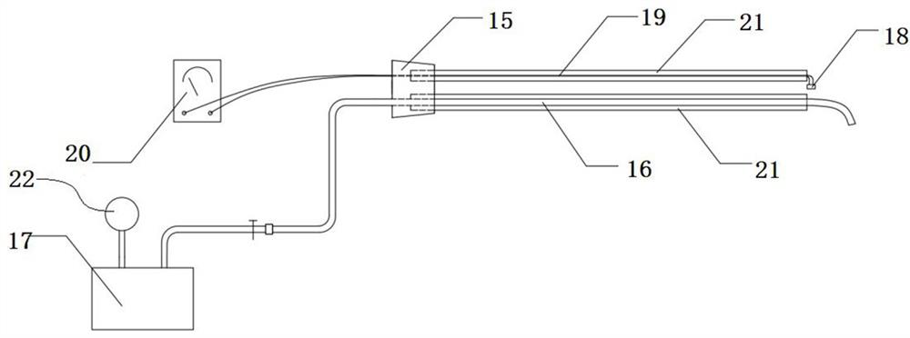
[0049] Such as Figure 3-4 As shown, the monitoring acquisition unit 2 includes a rubber plug 15 that is fitted to the monitoring conduit 1, and the glue plug 15 can be blocked in the monitoring conduit 1; the temperature measurement wire 19 is in the rubber plug 15; bundle The tube 16 is connected to the gas automatic negative pressure sampler 17 (Model: CFZ-30) along the end of the empty lane, and the other end of the beam tube 16 is blended with the monitoring pipe 1, extending in the vacuum area. On the side; the temperature warping wire 19 is connected to the explosion-proof multimeter 20 (model Metraline EXM 25A) close to the empty lane, and the temperature control probe 18 is connected, the explosion-proof multi-purpose table 20 is connected by temperature measurement wire 19 The probe 18 forms a set of monitoring devices, and after the glue plug 15 is mounted with the monitoring pipe 1, the temperature measurement probe 18 extends on one side of the v...


PUM


Abstract

The invention relates to the technical field of gob gas and temperature monitoring, in particular to a gob-side entry retaining side gob collection device and method. Comprising a plurality of monitoring pipelines which are poured and pre-embedded in a supporting wall body, and a monitoring acquisition unit which is used for acquiring gas and temperature data of a goaf, and the monitoring acquisition unit is detachably matched with the plurality of monitoring pipelines so as to perform temperature gas acquisition on different areas; the invention provides a gob-side entry retaining side goaf collection device and method, and the method comprises the steps: pre-burying a plurality of monitoring pipelines in a supporting wall, and carrying out the gas monitoring and temperature monitoring of a goaf through a portable monitoring collection unit; finally, the gob-side entry retaining side spontaneous combustion three-zone range of the gob is quickly and accurately judged.

Description

technical field [0001] The invention relates to the technical field of gob gas and temperature monitoring, in particular to a gob collecting device and method at the side of gob-side entry retention. Background technique [0002] At present, in order to reduce the waste of coal resources and control the problem of gas accumulation in corner corners, some coal enterprises in my country have adopted the technology of pouring retaining walls along the goaf to mine coal seams, that is, pouring retaining walls on the side of the gob roadway, retaining The roadway serves the next working face; most of the current bundle tube monitoring technologies require laying pipelines in advance, and the gas and temperature monitoring can only be carried out after the working face advances to form a goaf, and the working face advances often takes 20 days The above can only be completed, which leads to the problem that the measurement cycle is too long, and the collapse of the goaf can easily de...

Claims


Application Information

Patent Timeline
IPC IPC(8): G01D21/02
CPCG01D21/02
Inventor 吴祥业王婧雅庞政王帅孙鹏刘志雄
Owner INNER MONGOLIA UNIV OF SCI & TECH
Why Eureka
Try Eureka