Anesthetic gas monitoring device

An anesthetic gas and monitoring device technology, applied in the field of medical equipment, can solve the problems of complex transmission devices, less than expected anesthesia effect, and affecting patients' anesthesia effect, so as to ensure the effect of anesthesia

Inactive Publication Date: 2022-03-18
吴亚辉
View PDF0 Cites 0 Cited by
  • Summary
  • Abstract
  • Description
  • Claims
  • Application Information

AI Technical Summary

Problems solved by technology

The existing anesthetic gas transmission device has certain defects in actual use. When transmitting anesthetic gas to patients, the transmission device is relatively complicated. Too much anesthetic gas introduction will cause harm to the patient's body, and it is rare that the expected anesthesia effect cannot be achieved.
Therefore, it is necessary for medical staff to observe the amount of anesthetic gas delivered at all times, which greatly increases the burden on medical staff. Because the amount of anesthetic gas that needs to be introduced is different for different patients, and it is difficult to control the amount of gas relatively accurately during the transmission of anesthetic gas. Transmission volume, thus affecting the patient's anesthesia effect

Method used


Image

  • Anesthetic gas monitoring device
  • Anesthetic gas monitoring device
  • Anesthetic gas monitoring device

Examples


Embodiment Construction

[0025] The following will clearly and completely describe the technical solutions in the embodiments of the present invention with reference to the accompanying drawings in the embodiments of the present invention. Obviously, the described embodiments are only some of the embodiments of the present invention, not all of them. Based on the embodiments of the present invention, all other embodiments obtained by persons of ordinary skill in the art without making creative efforts belong to the protection scope of the present invention.

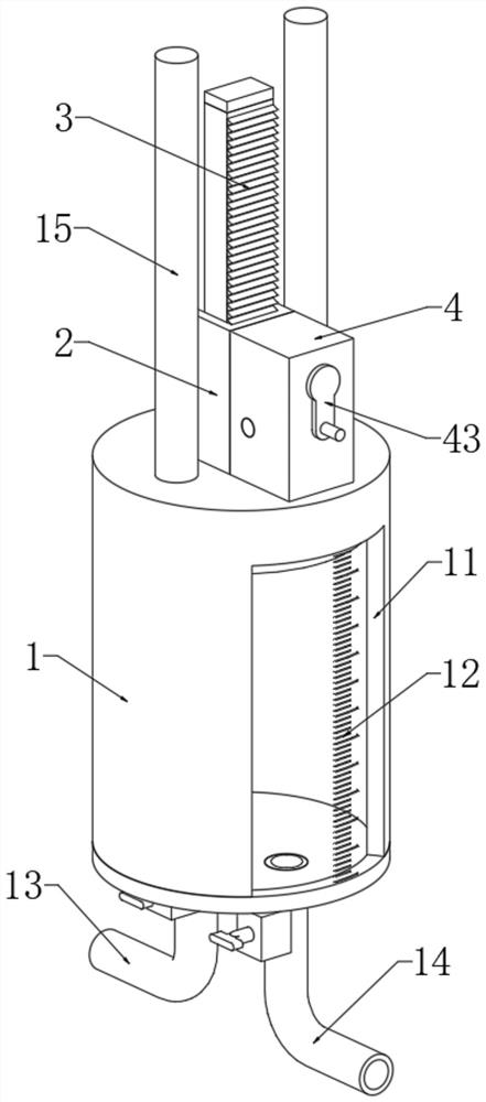
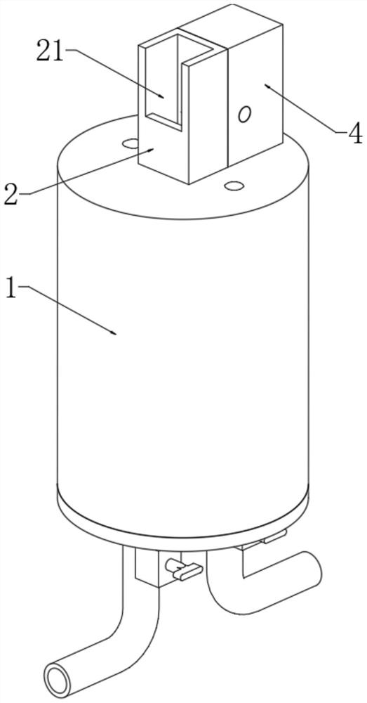
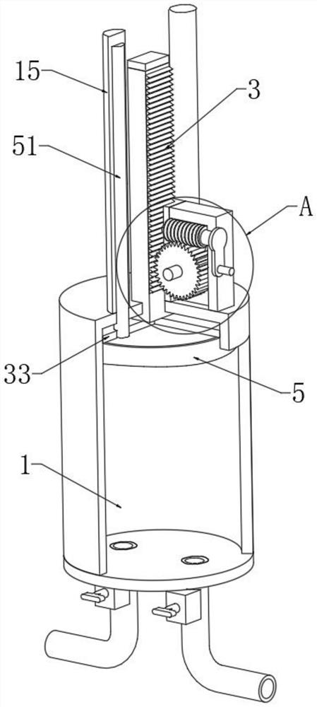
[0026] see Figure 1 to Figure 6 , the present invention provides a technical solution: an anesthetic gas monitoring device, including an anesthetic gas transfer tank 1, a transparent plate 11 is embedded in the side of the anesthetic gas transfer tank 1, a scale 12 is arranged on the side of the transparent plate 11, and the anesthetic gas The lower end of the transfer tank 1 is plugged with an inlet pipe 13 and an outlet pipe 14, and the inlet ...


PUM


Abstract

The invention relates to the technical field of medical instruments, in particular to an anesthetic gas monitoring device which comprises an anesthetic gas transfer tank, a transparent plate is embedded in the side face of the anesthetic gas transfer tank, a dial gauge is arranged on the side face of the transparent plate, and a gas inlet pipe and a gas outlet pipe are inserted into the lower end of the anesthetic gas transfer tank. The anesthetic gas transferring device has the beneficial effects that anesthetic gas is filled into an inner cavity of the anesthetic gas transferring tank through the gas inlet pipe, the anesthetic gas pushes the piston to slide upwards along the inner cavity of the anesthetic gas transferring tank, the anesthetic gas transferring tank moves upwards, and the anesthetic gas transferring tank moves upwards along the inner cavity of the anesthetic gas transferring tank; when the piston is in contact with the limiting circular plate, filling of the anesthetic gas into the anesthetic gas transfer tank is stopped, at the moment, a positioning block of the positioning mechanism is connected with a positioning rod of the piston mechanism in an inserted mode, so that the piston is fixed, the amount of the anesthetic gas in the anesthetic gas transfer tank is fixed, and therefore the introduction amount of the anesthetic gas can be controlled relatively accurately.

Description

technical field [0001] The invention relates to the technical field of medical devices, in particular to an anesthetic gas monitoring device. Background technique [0002] In existing clinical operations, patients need to be anesthetized first. Anesthesia refers to the process of injecting anesthetics into the body through inhalation, intravenous, intramuscular injection or rectal perfusion to suppress the central nervous system, resulting in the loss of consciousness of the patient and no pain in the whole body. The most commonly used anesthesia method is general anesthesia with endotracheal intubation, which is characterized by the use of intravenous anesthetics or inhalational anesthetics to produce general anesthesia, and tracheal intubation and mechanically assisted breathing are required during the operation. The existing anesthetic gas transmission device has certain defects in actual use. When transmitting anesthetic gas to patients, the transmission device is relat...

Claims


Application Information

Patent Timeline
Patent Type & Authority Applications(China)
IPC IPC(8): A61M16/01
CPCA61M16/01A61M16/0003
Inventor 吴亚辉
Owner 吴亚辉
Why Eureka
Try Eureka