
Welding clamp and matched feeding and discharging tool thereof

A welding fixture and tooling technology, applied in welding equipment, auxiliary welding equipment, welding/cutting auxiliary equipment, etc., can solve the problems of low production efficiency, high repetitive labor intensity, limited time saving, etc., and achieve high clamping work efficiency, The effect of improving work efficiency and improving production efficiency

Pending Publication Date: 2022-03-18
广东诺巴特智能设备有限公司
View PDF7 Cites 0 Cited by
  • Summary
  • Abstract
  • Description
  • Claims
  • Application Information

AI Technical Summary

Problems solved by technology

[0002] In the prior art, when the welding machine performs the welding operation on the workpiece, the two workpiece products to be welded need to be clamped and fixed, and the design of the welding fixture generally needs to be designed according to the specific product, such as welding on both sides of the shell. The bent plates are welded on both sides of the shell. The conventional design requires the use of three clamping mechanisms, which are used to clamp the shell workpiece and two bent plates respectively. The three clamping mechanisms are located on one base. Each clamping and positioning requires It takes a long time to operate three times, the operation efficiency is low, and the labor intensity of the workers is high
[0003] The workpieces on the welding fixture are generally picked and placed manually. For mass production, workers have high repetitive labor intensity, time-consuming and low production efficiency.
Therefore, robots are generally used to assist in clamping the workpiece for pick-and-place. For the process of welding the bent plate on the side of the shell, it is generally necessary to design at least two robots to clamp the shell and the bent plate respectively. Sequential pick-and-place operation, taking a welding jig of a shell piece as an example, it is necessary to grab the shell piece from the raw material area and place it on the shell piece station of the welding fixture, and then take the two bent plates sequentially and place them To the bending plate station of the welding fixture, the bending plate is located on the side of the shell part. From the above operations, it can be seen that although the current conventional robot-assisted clamping design saves labor, the operation process is also relatively complicated and the time saving is limited.

Method used


Image

  • Welding clamp and matched feeding and discharging tool thereof
  • Welding clamp and matched feeding and discharging tool thereof
  • Welding clamp and matched feeding and discharging tool thereof

Examples


Embodiment 2

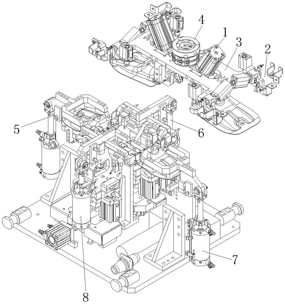
[0035] Embodiment 2. On the basis of the technical solution of Embodiment 1, the specific structure of the first clamping mechanism 5 of the welding fixture of the present invention is that the first support plate 53 is vertically arranged on the base 9, and the first support plate 53 is vertically arranged on the base 9. The plate 53 includes a vertical plate and a horizontal plate, and the first cylinder 51 is rotatably connected to the side of the first supporting plate 53 , that is, the side of the vertical plate, through the mounting seat. Further, the opening on the side of the first support plate 53, that is, the opening on the upper side of the riser, the mounting seat of the first cylinder 51 is connected to the side opening of the first support plate 53 through a pivot, that is, the mounting seat passes through Pivot to the side opening of the side panel.

[0036] Further, the telescopic shaft of the first cylinder 51 is pivotally connected to the pivot hole opened o...

Embodiment 3

[0037] Embodiment 3, on the basis of the technical solution of Embodiment 2, the welding fixture of the present invention, the specific structure of the second clamping mechanism 6 is that the second support plate 64 is vertically arranged on the base 9, and the second cylinder 61 is pivotally connected to the side hole of the second support plate 64 . Further, the telescopic shaft of the second air cylinder 61 is pivotally connected to the pivot hole provided on the second clamping plate 63 . Further, the upper end of the second rocking plate 62 is rotatably connected to the second clamping plate 63 through a pin shaft, and the lower end of the first rocking plate 54 is rotatably connected to the top of the second support plate 64 through a pin shaft. Since the bent plate 21 is a bent plate 21 with a small structural size, the bent plate 21 can be clamped on the second clamping plate 63 by positioning pins and bolts, and the bent plate 21 is placed on the shell member 16 The...

Embodiment 5

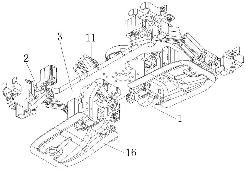
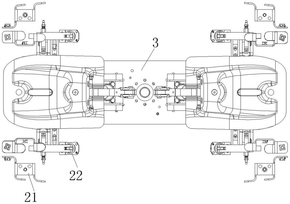
[0042] Embodiment five, such as Figure 1-4 As shown, on the basis of the technical solution of Embodiment 4, the specific structure of the first gripper 1 of the loading and unloading tooling of the present invention is that the first cylinder 11 is installed obliquely, the second cylinder 12 and the first support plate 15 are arranged perpendicular to the base plate 3 , the ejector rod 17 is arranged parallel to the first support plate 15 , and the ejector rod 17 withstands the middle part of the shell member 16 . The first cylinder 11 is hinged to the splint 13 through the telescopic shaft, and the angle between the telescopic shaft and the push rod 17 is an acute angle, and the specific angle parameters are set according to actual production needs. Both ends of the third rocking plate 14 are respectively hinged to the first supporting plate 15 and the splint 13 . The two ends of the third rocking plate 14 are hinged, and the movable plate 24 is equivalent to a lever. The ...


PUM


Abstract

The welding clamp comprises a base, a clamping assembly is arranged on the base and used for clamping a shell part to be welded and a bent plate, the clamping assembly comprises a first clamping mechanism, a second clamping mechanism, a third clamping mechanism and a fourth clamping mechanism, and the first clamping mechanism and the third clamping mechanism are oppositely arranged and are the same in structure; the second clamping mechanism and the fourth clamping mechanism are oppositely arranged and have the same structure; a first air cylinder on the first clamping mechanism drives a first clamping plate to rotate and is matched with the top of the first supporting plate so as to clamp the shell part. A bending plate is fixed to a second clamping plate on the second clamping mechanism, and the bending plate is arranged on the side portion of the shell part to wait for a welding machine to weld and fix the shell part and the bending plate. According to the device, synchronous clamping is achieved through the four clamping mechanisms, mounting and positioning of the two shell parts and the bent plates on the two sides can be completed, the clamping work efficiency is high, the two shell parts can be synchronously grabbed through the matched feeding and discharging tool, a welding clamp is matched, and the work efficiency of the whole production line is improved.

Description

technical field [0001] The invention relates to the technical field of improved design of equipment used in loading and unloading and fixture clamping processes in a welding production line, in particular to a welding fixture and its supporting loading and unloading tooling. Background technique [0002] In the prior art, when the welding machine performs the welding operation on the workpiece, the two workpiece products to be welded need to be clamped and fixed, and the design of the welding fixture generally needs to be designed according to the specific product, such as welding on both sides of the shell. The bent plates are welded on both sides of the shell. The conventional design requires the use of three clamping mechanisms, which are used to clamp the shell workpiece and two bent plates respectively. The three clamping mechanisms are located on one base. Each clamping and positioning requires It takes a long time to operate three times, the operation efficiency is lo...

Claims


Application Information

Patent Timeline
Patent Type & Authority Applications(China)
IPC IPC(8): B23K37/04B23K37/00
CPCB23K37/04B23K37/00
Inventor 余鹏包春晶
Owner 广东诺巴特智能设备有限公司
Learn More