Machining method for frame parts

A technology of machining and parts, applied in the field of machining of frame parts, can solve problems such as machining deformation of frame parts, and achieve the effect of solving machining deformation, improving machining efficiency and stable product quality

Pending Publication Date: 2022-03-18
SHAANXI ELECTRICAL APPLIANCE RES INST
View PDF8 Cites 0 Cited by
  • Summary
  • Abstract
  • Description
  • Claims
  • Application Information

AI Technical Summary

Problems solved by technology

[0004] In view of this, the present invention provides a mechanical processing method for frame parts, which solves the problem of processing deformation of f

Method used


Image

  • Machining method for frame parts
  • Machining method for frame parts
  • Machining method for frame parts

Examples


Embodiment Construction

[0028] The present invention will be described in detail below with reference to the accompanying drawings and examples.

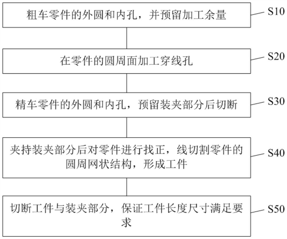
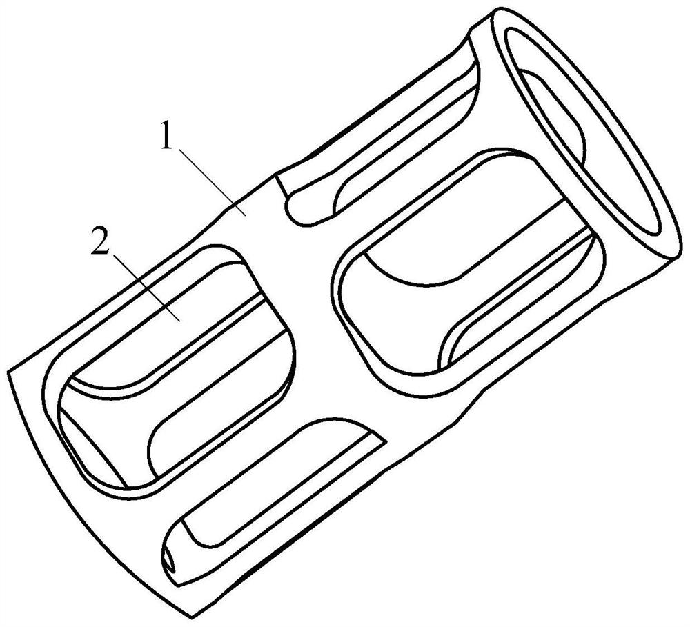
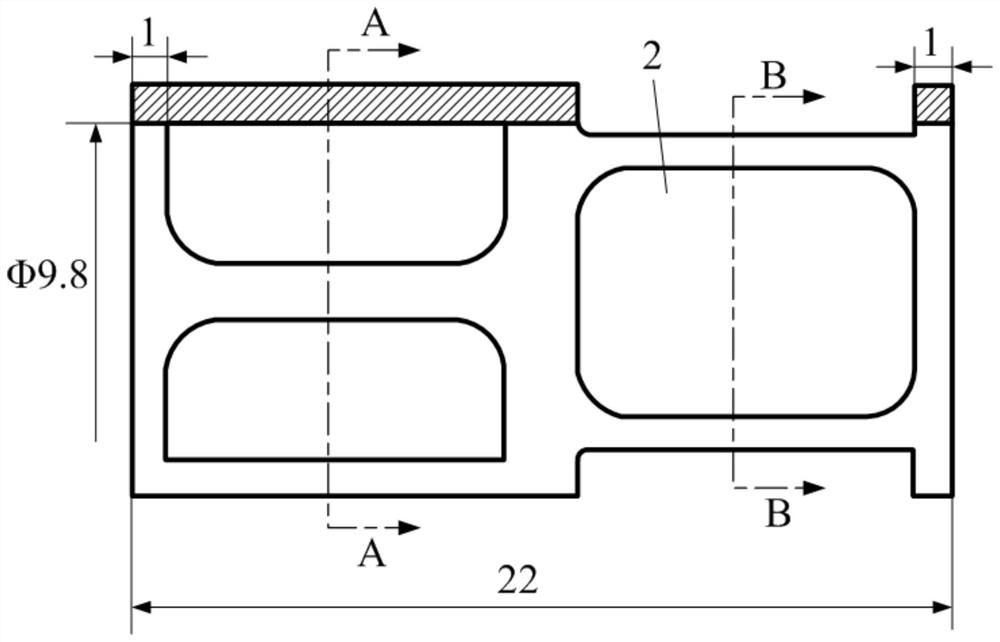
[0029] Such as figure 1 As shown, the present invention provides a kind of mechanical processing method of frame type part 1, and the finished product structure of frame type part 1 is as follows figure 2 As shown, the frame part 1 is a sleeve provided with a plurality of hollow windows 2, and the cross-sectional view of the frame part 1 is as follows image 3 , Figure 4 and Figure 5 As shown in the structure; the machining method comprises the following steps:

[0030] Step S10, roughing the outer circle and inner hole of the part, and reserving machining allowance; preparing the blank of the frame part 1 can be a sleeve or cylinder; roughing the outer circle and inner hole of the blank, and then During the processing process, it is necessary to reserve a machining allowance for finishing machining; when roughing the outer circle and inner hole of ...


PUM


Abstract

The invention discloses a machining method of a frame part, which comprises the following steps of: roughly turning an outer circle and an inner hole of the part, and reserving machining allowance; threading holes are formed in the circumferential surface of the part; the outer circle and the inner hole of the part are subjected to finish turning, stress deformation generated during threading hole manufacturing is repaired while burrs are removed, it is guaranteed that the part meets the requirements for design size precision and form and location tolerance, and cutting is conducted after a clamping part is reserved; after the clamping part is clamped, the part is aligned, the circumferential net structure of the part is linearly cut, and a workpiece is formed; and the workpiece and the clamping part are cut off to ensure that the length size of the workpiece meets requirements. According to the machining method, the problem of machining deformation of the frame parts is solved, the product quality is stable, the requirements of design drawings are met, and the product percent of pass and the machining efficiency are improved.

Description

technical field [0001] The invention relates to the technical field of machining, in particular to a machining method for frame parts. Background technique [0002] Frame parts are common types in machining. In recent years, with the development of my country's aerospace industry, the application proportion of such parts has increased year by year. In order to reduce the weight of parts in aerospace applications, and because the material is mostly the national military standard stainless steel 1Cr18Ni9Ti, the parts have the characteristics of small size, thin wall, difficult processing, and high precision of matching dimensions. Since the circumferential network structure is easily deformed during the milling process, it is difficult to guarantee the dimensional tolerance and shape tolerance accuracy of the product, and cannot meet the design requirements. The main difficulties in processing this part are: more allowances for removing the circumferential network structure,...

Claims


Application Information

Patent Timeline
IPC IPC(8): B23P15/00B23Q3/06
CPCB23P15/00B23Q3/06
Inventor 胡强辉吴亚男田衡蔡阔阔
Owner SHAANXI ELECTRICAL APPLIANCE RES INST
Why Eureka
Try Eureka