Precise trimming device for section of end part of spliced protective fence

A technology of end section and dressing device, which is applied to machine tools suitable for grinding workpiece edges, grinding drive devices, and parts of grinding machine tools, etc. and other problems, to achieve the effect of reducing angle error, good versatility, and improving ease of use

Pending Publication Date: 2022-03-18
天长市锦瑞防护设施有限公司
View PDF15 Cites 1 Cited by
  • Summary
  • Abstract
  • Description
  • Claims
  • Application Information

AI Technical Summary

Problems solved by technology

[0003] When the guardrail is manufactured, it is often necessary to trim the butt ends well. Whether it is a guardrail built with profiles or a spliced ​​guardrail formed by cutting angle steel, a bad end section will lead to excessive splicing of the guardrail. The problem of gaps, too large gaps in the guardrail connected by corner fittings will affect the appearance, and the solution of welding connection will lead to the problem of reduced strength of the connection. The common cutting solution is to use a sawing machine or a cutting machine to cut directly. The angle of the end face is formed by cutting to the direction, and this cutting scheme is difficult to obtain a relatively good end section. Using the engraved line as a reference and grinding with an angle grinder can also obtain a slightly better quality end face of the guardrail, but this scheme The operation is difficult and relies heavily on manpower. Another solution is to directly use the laser cutting machine to cut the material of the guardrail to achieve a good cross-section, but the laser cutting machine is too large to move quickly with the engineers, and the laser cutting machine is usually only suitable for It is less efficient to process hollow guardrail raw materials and form a good cross-section in the face of semi-solid steel or aluminum

Method used


Image

  • Precise trimming device for section of end part of spliced protective fence
  • Precise trimming device for section of end part of spliced protective fence
  • Precise trimming device for section of end part of spliced protective fence

Examples


Embodiment Construction

[0039] Next, the technical solutions in the embodiments of the present invention will be described in connection with the drawings of the embodiments of the present invention, and it is understood that the described embodiments are merely the embodiments of the present invention, not all of the embodiments.

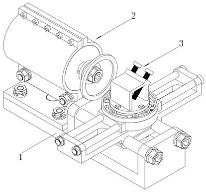
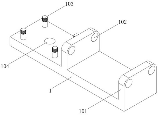
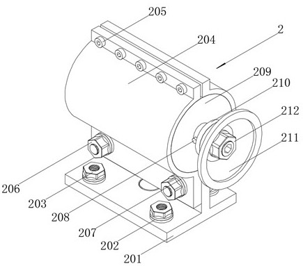
[0040] refer to Figure 1 - Figure 15 A precision trimming device for the end section of the splicing protective bar, including the support assembly 1 and the grinding assembly 2 and the clamp assembly 3 disposed thereon, and two grinding assemblies in the support assembly 1 are vertical. The bottom plate 101, the upper end of the bottom plate 101 opens a bottom plate aperture hole 102, wherein one bottom plate 101 is located at the end of the support assembly 1, and the other end of the support assembly 1 is provided with four vertical bottom bolts 103, support The assembly 1 opens the bottom plate vertical hole 104 at the midpoint of the four bottom bolts 103, the grinding a...


PUM


Abstract

The precise trimming device comprises a supporting assembly, a grinding assembly and a clamping assembly, the grinding assembly and the clamping assembly are arranged above the supporting assembly, two bottom vertical plates perpendicular to the grinding assembly are arranged above the supporting assembly, and bottom plate horizontal holes are formed in the upper ends of the bottom vertical plates; wherein one bottom vertical plate is located at the end of the supporting assembly, four vertical bottom bolts are arranged at the other end of the supporting assembly, bottom plate vertical holes are formed in the positions, at the midpoints of the diagonal lines of the four bottom bolts, of the supporting assembly, the grinding assembly comprises a horizontal plate and a machine clamping cylinder, and the machine clamping cylinder is located above the horizontal plate. The horizontal plate is connected with the machine clamping cylinder through a vertical nut and a vertical gasket, a motor is fixed in the machine clamping cylinder through a cylinder locking screw, and a connecting shaft is fixed in an output shaft of the motor. According to the precise trimming device for the section of the end of the spliced type protective fence, precise angle trimming of the end of a part of the spliced type protective fence can be achieved, and the precise trimming device is suitable for being widely used and popularized.

Description

Technical field [0001] The present invention belongs to the field of manufacturing techniques, and in particular to a precision trimming device for the end portion of the splicing protective bar. Background technique [0002] The protective bar is mainly used in the protection and protection of equipment and facilities between factories, workshops and warehouse. Common steel, such as circular steel pipes, square steel pipes or shaped steel sheets, and surface treatment processes are typically a fully automatic electrostatic powder spray or paint, while the raw material used in the surface treatment of the collision guardrail is a waterproof material. [0003] The guard field often needs to make good trims at the time of manufacturing, whether using the guardrail built by the profile or the splice that uses the angle steel cutting, the non-good end section will lead to excessive stagnation The problem of gaps, excessive gaps in the guardrail using the angle part can affect the app...

Claims


Application Information

Patent Timeline
Patent Type & Authority Applications(China)
IPC IPC(8): B24B9/04B24B41/04B24B41/06B24B47/22
CPCB24B9/04B24B41/06B24B47/22B24B41/04
Inventor 李福才缪玉云
Owner 天长市锦瑞防护设施有限公司
Why Eureka
Try Eureka