Speed reduction device

A deceleration device and main channel technology, applied in the direction of brake type, brake parts, liquid resistance brake, etc., can solve the problems of low power conversion efficiency, large noise and vibration, etc., to improve power conversion efficiency, improve efficiency, improve The effect of acceleration

Pending Publication Date: 2022-03-18
HUAIBEI KANGHUI ELECTRONIC TECH CO LTD
View PDF0 Cites 1 Cited by
  • Summary
  • Abstract
  • Description
  • Claims
  • Application Information

AI Technical Summary

Problems solved by technology

[0003] The purpose of the present invention is to provide a reduction gear, which solves the prob

Method used


Image

  • Speed reduction device
  • Speed reduction device
  • Speed reduction device

Examples


Embodiment 1

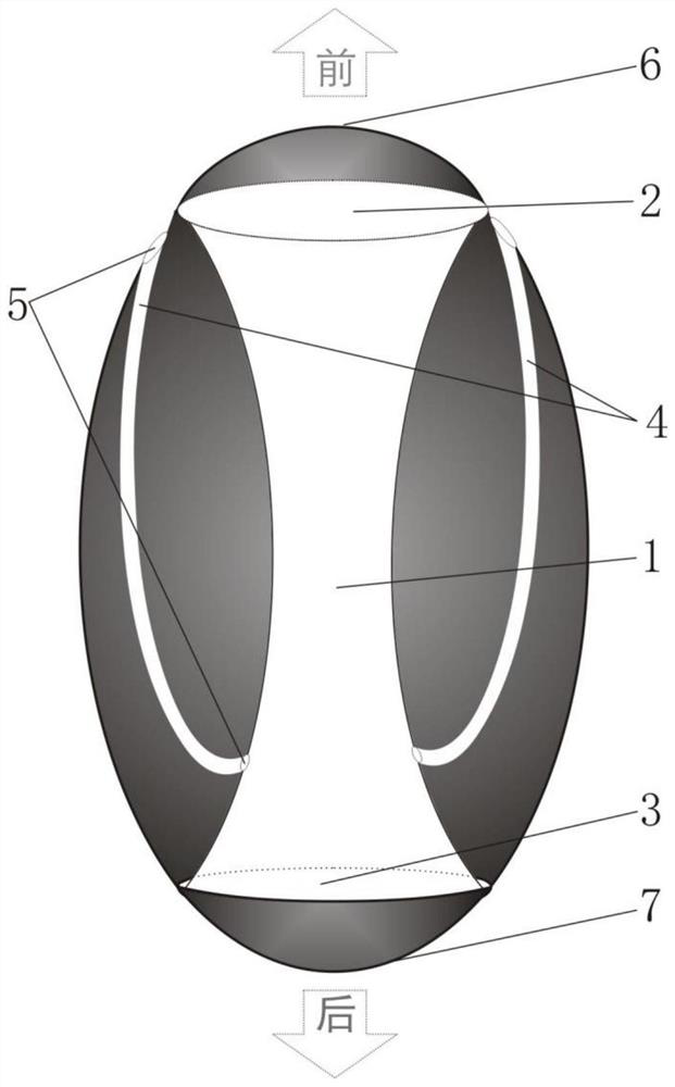
[0030] Such as figure 1 As shown, a deceleration device is the most commonly used deceleration device, including a main channel 1, the main channel 1 forms a front port 2 of the main channel at the front end of the deceleration device, and a rear port 3 of the main channel is formed at the rear end of the deceleration device, and The front port 2 of the main channel and the rear port 3 of the main channel are respectively provided with a controllable open front cover 6 and a rear cover 7. There are also two or more front return channels 4 in the reduction gear, and one port of the front return channel 4 It is connected to the inner wall of the main passage 1 by obliquely cutting towards the front mouth 2 of the main passage, and a valve 5 is provided at the connection. 1 The front openings have the same or similar orientation.

[0031] When the forward-moving deceleration device needs to decelerate, open the front cover 6, close the rear cover 7, open the valve 5, and the flu...

Embodiment 2

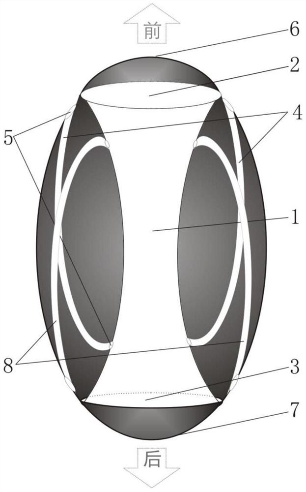
[0034] Such as figure 2 As shown, a deceleration device capable of bidirectional deceleration, on the basis of the structure of Embodiment 1, further: the deceleration device further includes a rear return passage 8, and there are two or more rear return passages 8, one port of which is directed toward The direction of the rear port 3 of the main passage is obliquely connected to the inner wall of the main passage 1, and a valve 5 is provided at the connection. The rear mouth is facing the same or similar.

[0035] When the deceleration device moving backward needs to be decelerated, the rear outer cover 7 is opened, the front outer cover 6 is closed, and the valve 5 is opened, and the fluid entering the main channel 1 is discharged in the reverse direction through the rear return channel 8, generating a backward thrust to realize rearward movement. Slow down toward a moving object.

[0036] This embodiment is a deceleration device with two-way deceleration function of a si...

Embodiment 3

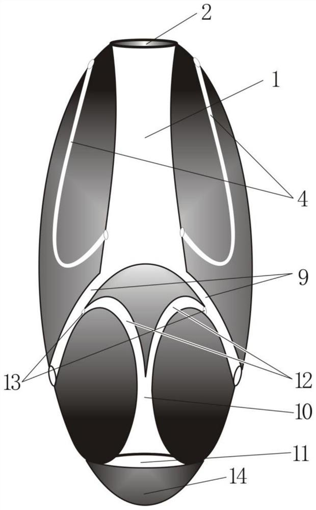
[0038] Such as image 3 As shown, a deceleration device capable of bidirectional deceleration, on the basis of the structure of Embodiment 1, further: the rear section of the main passage 1 is formed with two or more discharge passages 9, and the rear end of the discharge passage 9 is decelerating The rear side of the limit of the device forms an obliquely cut backward exhaust port; the middle position of the rear end of the deceleration device is also provided with a rear air inlet 11, and the rear air inlet is provided with a rear air inlet cover 14; 11 connected rear air intake channel 10 extends inward and divides into two or more rear air intake channel branches 12, and the rear air intake channel branch 12 communicates with the exhaust port 9 in the direction of the exhaust port of the exhaust channel 9 The inner wall, and a branch valve 13 is provided at the communication point;

[0039] When the deceleration device decelerates backwards, the rear air intake cover 14 i...


PUM


Abstract

The speed reduction device comprises a main channel, a main channel front opening is formed in the position, at the front end of the speed reduction device, of the main channel, a main channel rear opening is formed in the rear end of the speed reduction device, two or more front backflow channels are further arranged in the speed reduction device, and one end opening of each front backflow channel is communicated with the inner wall of the main channel in a beveling mode in the direction facing the main channel front opening. The other port of the front backflow channel is led out from the front end position of the speed reduction device, and the direction of the leading-out port is the same as or close to the direction of the front opening of the main channel. The speed reducer adopts the structure of the front backflow channel and the rear backflow channel, so that in the speed reduction process, reverse thrust of fluid can be fully utilized, the speed reduction efficiency is improved, and dependence on reverse thrust of a brake parachute and an internal machine is reduced; the inner wall of each channel of the speed reducer adopts a rotatable spherical convex surface structure, so that the friction force between fluid and the inner wall can be reduced, turbulent flow and turbulent flow generated when the fluid moves in a pipeline are reduced, the vibration and noise of a machine are reduced, and the power conversion efficiency is improved.

Description

technical field [0001] The invention relates to the technical field of mechanical motion, in particular to a speed reduction device. Background technique [0002] Speed ​​reduction devices are used in many devices, such as aircraft, ships, submersibles, and various vehicles. The existing reduction device has low power conversion efficiency during operation and still produces significant noise and vibration, which is caused by defects in its internal and external structures. Contents of the invention [0003] The object of the present invention is to provide a reduction gear, which solves the problems of low power conversion efficiency, large noise and vibration existing in the existing reduction gear. [0004] The present invention achieves the above object through the following technical solutions: [0005] A deceleration device, comprising a main passage, the main passage forms a front opening of the main passage at the front end of the deceleration device, forms a rea...

Claims


Application Information

Patent Timeline
IPC IPC(8): F16D57/00F16D65/00
CPCF16D57/00F16D65/0006
Inventor 吴剑飞吴本华
Owner HUAIBEI KANGHUI ELECTRONIC TECH CO LTD
Why Eureka
Try Eureka