Shield tunnel model test device and method

A model test device, shield tunnel technology, applied in measuring devices, instruments, mapping and navigation, etc., can solve the problems of large difference in stiffness of each ring, unsuitable deformation, inconsistent force mechanism, etc., to facilitate disassembly and installation. , easy to shovel and improve efficiency

Pending Publication Date: 2022-03-18
NINGBO METRO GRP
View PDF3 Cites 1 Cited by
  • Summary
  • Abstract
  • Description
  • Claims
  • Application Information

AI Technical Summary

Problems solved by technology

[0004] 2. The shear strength of the actual shield tunnel joint is mainly provided by the concave and convex tenons on both sides of the segment, while the existing assembled model tunnels are mostly cut with rubber tubes or plexiglass tubes, without concave and convex tenon structures, and their stress mechanism is similar to that of The actual segments are inconsistent
[0005] 3. The existing assembled model tunnels are mainly connected by screws and nuts, and the stiffness of the joints depends on the degree of manual tightening of the screws and nuts. Therefore, the stiffness of each ring of this spliced ​​tunnel is quite different, and it is not suitable for simulating multi-ring pipes. Deformation of a tunnel composed of sheets under external loads
[0006] 4. The existing prefabricated model tunnels are full of screws and nuts inside and outside, which will seriously hinder the installation of dial indicators in the model tunnels
[0008] Application No. 201710270578.2 "A Mold for Tunnel Model Test Shield Segment Preparation", this device overcomes the shortcomings that the previous lining segments cannot be made in blocks and cannot measure the force status of the circumferential and longitudinal steel bars between the lining segments

Method used


Image

  • Shield tunnel model test device and method
  • Shield tunnel model test device and method
  • Shield tunnel model test device and method

Examples


Embodiment 1

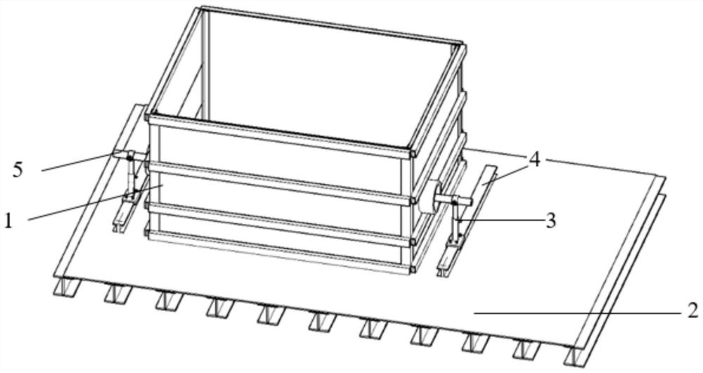
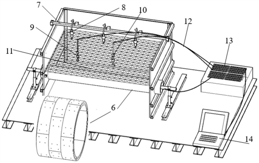
[0068] Embodiment 1 of the present application provides a shield tunnel model test device, using 3D printing technology to produce a complete set of model test devices that can truly simulate the external load of a shield tunnel under various stratum environments. The model tunnel segment The force mechanism is consistent with the actual tunnel segment, the manual assembly is relatively simple, and the displacement gauge is easy to install inside the tunnel. Its structure includes model box 1, base 2, reference rod fixed support 3, slide rail 4, tunnel displacement reference rod 5, model tunnel 6, soil top surface settlement reference rod 7, soil top surface settlement percentage indicator 8, Micro earth pressure gauge 9, micro pore water pressure gauge 10, simulated soil 11, sensor wire 12, signal acquisition instrument 13, computer 14.

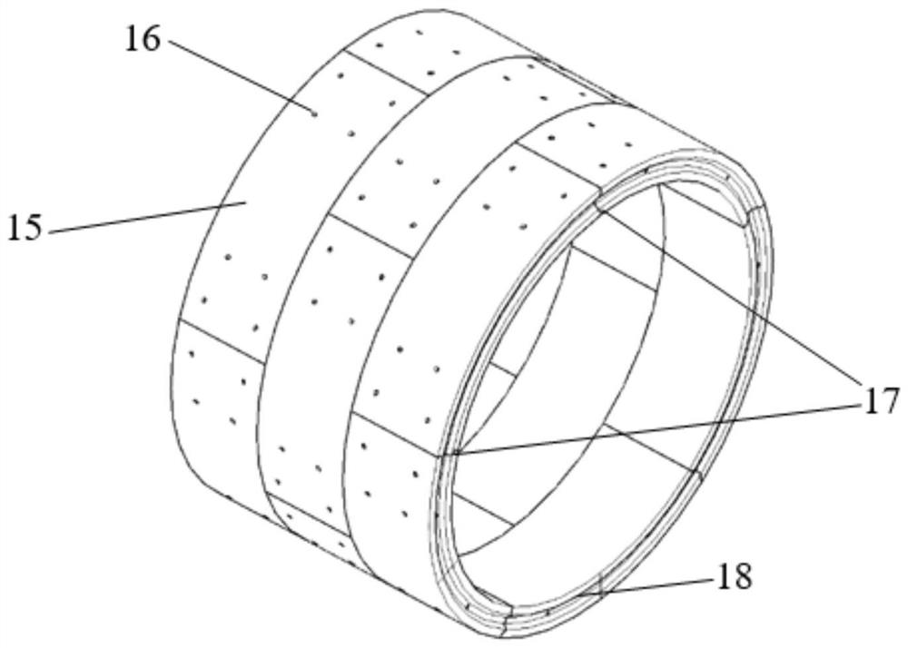
[0069] Firstly, the printing of the model tunnel segment 15 is carried out. Draw the segment model file on the computer, the inner diamete...

Embodiment 2

[0078] Embodiment 2 of the present application provides a method for installing a shield tunnel model test device, comprising the following steps:

[0079] S1. Purchasing a sufficient amount of fine sand, gypsum, fly ash, and barite powder according to the test needs to ensure that the test site is connected to water and electricity. Pour fine sand, gypsum, fly ash, barite powder and water into the mixing tank according to the proportion, and use a mixer to stir the materials in the tank. After the mixing is completed, the materials are mixed into mud water, and these mud water is poured into the large material Leave to stand in a bucket. After standing still for a week, scoop up the clear water on the inner surface of the bucket to prepare the simulated soil 11.

[0080]S2. Weld the four columns 31 to the base 2, and insert the front and rear baffles 30 of the model box into the front and rear baffle slots of the columns 31. First insert the lower plate 27 of the two plexig...


PUM


Abstract

The invention relates to a shield tunnel model test device which comprises a model tunnel, simulated soil, a model box, a tunnel deformation test system and other test instruments. The model tunnel is formed by splicing a plurality of model tunnel segments; the model box is formed by splicing a stand column, a model box front baffle plate, a model box rear baffle plate and an organic glass plate; the tunnel deformation testing system is composed of a displacement meter, a tunnel displacement reference rod, a signal acquisition instrument, a reference rod fixing support and a sliding rail. The other testing instruments comprise a soil body top surface settlement reference rod, a soil body top surface settlement dial indicator, a miniature soil pressure gauge and a miniature pore water pressure gauge. The model tunnel has the beneficial effects that the model tunnel is formed by splicing the model tunnel segments, the model tunnel segments are manufactured completely according to the appearance characteristics of the actual tunnel segments, and the model tunnel formed by splicing the model tunnel segments is consistent with the actual tunnel in the aspect of stress deformation.

Description

technical field [0001] The invention belongs to the field of tunnel engineering, in particular to a shield tunnel model test device and method. Background technique [0002] Restricted by the site environment and construction conditions, many scholars have used model tests to study the deformation of shield tunnels under external loads in various strata. Whether the model test can truly reflect the stress mechanism of the actual shield tunnel structure largely depends on the similarity of the model structure, so the production and materials of the model shield tunnel directly affect the reliability of the test results. Common model shield tunnels are divided into integral type and assembled type. The integral model tunnel is generally simulated by a whole iron pipe, plastic pipe or rubber pipe. The materials and production of these pipes are very convenient, but due to the rigidity of the pipe itself It is very large, and it needs to be deformed under the action of a huge e...

Claims


Application Information

Patent Timeline
IPC IPC(8): G01C5/00G01B21/02G01B21/32G01L11/00
CPCG01C5/00G01B21/02G01B21/32G01L11/00
Inventor 周晔叶俊能陆幸郦亮叶荣华钱峰刘干斌
Owner NINGBO METRO GRP
Why Eureka
Try Eureka