

Glass hot bending mold and glass hot bending method
A mold and glass technology, applied in the field of glass hot bending molds and glass hot bending, can solve the problems of difficulty in adjusting the temperature control accuracy of the glass surface, significant temperature gradient of the glass blank, and excessive temperature difference of the formed glass, so as to avoid excessive temperature gradients. Large, eliminate temperature gradient, reduce the effect of water ripples
- Summary
- Abstract
- Description
- Claims
- Application Information
AI Technical Summary
Problems solved by technology
Method used
Image

Examples
Embodiment 1
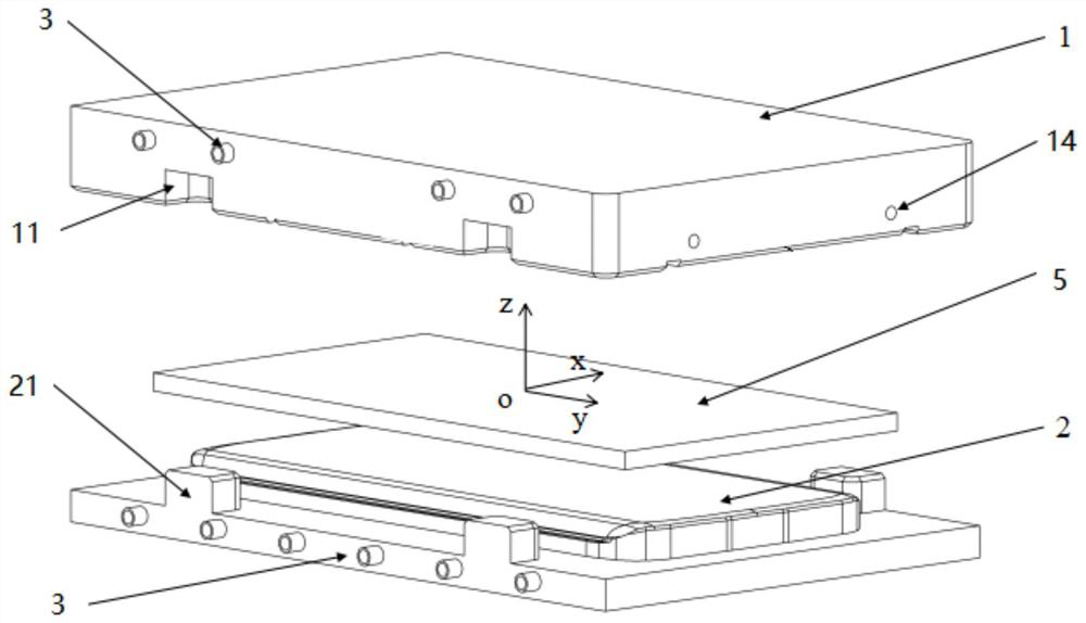
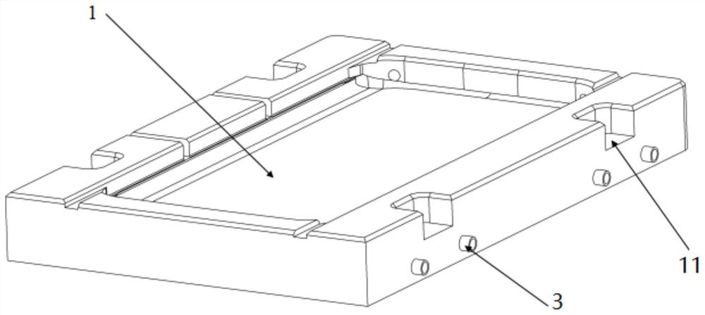
[0039] This embodiment provides a glass hot-bending mold, which includes a mold body, and the mold body includes an upper mold 1 and a lower mold 2; the upper mold 1 and the lower mold 2 are closed to form a sealed cavity; the upper mold 1 The side near the lower mold 2 is provided with four depressions 11; the four depressions 11 are arranged symmetrically about the yoz plane; the side of the lower mold 2 close to the upper mold 1 is provided with four protrusions 21; The four raised portions 21 are respectively opposite to the four depressed portions 11; the raised portions 21 of the lower mold 2 are engaged with the depressed portions 11 of the upper mold 1, so that the upper mold 1 and the lower mold 2 After closing the molds, a sealed cavity is formed, and the glass blank 5 is placed in the sealed cavity.
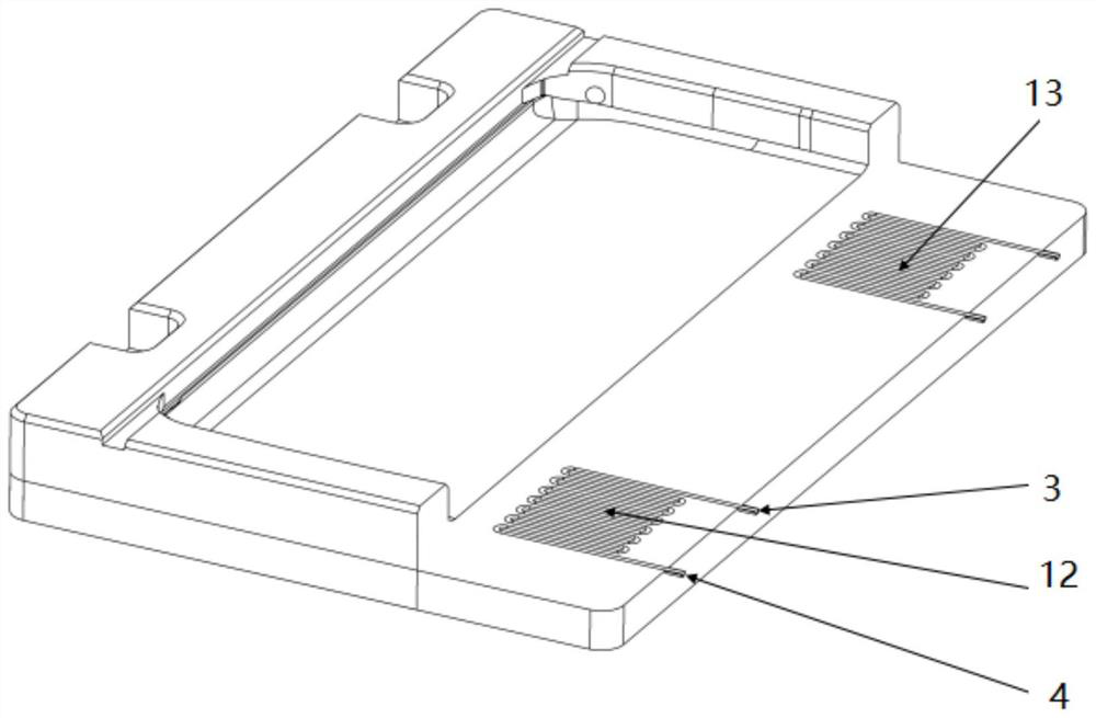
[0040] The upper mold 1 and the lower mold 2 are respectively provided with multiple sets of micro-channels, and nitrogen gas is fed into the micro-channels to elimina...
Embodiment 2
[0048] This implementation provides a method for hot-bending glass using the above-mentioned glass hot-bending mold, which includes the following steps.
[0049] S1. Put the glass blank 5 into the glass hot bending mold, and roughly heat it to the vicinity of the first preset temperature;
[0050] Specifically, put the glass blank to be processed into the corresponding position of the lower mold 2, align the upper mold 1 and the lower mold 2 in the oz direction, then close the upper mold 1 and the lower mold 2, and the upper mold 1. Refer to the position relationship between the lower mold 2 and the glass blank figure 1 As shown; the first preset temperature is set according to the processing conditions, and the entire environment is roughly heated to around the first preset temperature by the heat source.
[0051] When heating the glass blank 5, after the external heat source directly heats the mold body, the heat transfer of the mold body heats the glass blank 5, that is, t...
PUM
 Abstract
Description
Claims
Application Information