Building drainage structure

A technology for building drainage and No. 1, which is applied to buildings, water supply devices, pipe components, etc., can solve the problems of easily damaged connectors, affecting the indoor living environment, and water seals that cannot be used normally, so as to improve service life and improve indoor living. Environment, effect of quick installation and removal

Active Publication Date: 2022-03-22
江苏伟中景观建设有限公司 +1
View PDF7 Cites 0 Cited by
  • Summary
  • Abstract
  • Description
  • Claims
  • Application Information

AI Technical Summary

Problems solved by technology

[0008] In order to make up for the deficiencies of the existing technology and solve the problems that the existing connection between the horizontal pipe and the vertical pipe is easily damaged and the water seal cannot be used normally, which affects the indoor living environment, the present invention proposes a building drainage structure

Method used


Image

  • Building drainage structure
  • Building drainage structure
  • Building drainage structure

Examples


Embodiment 1

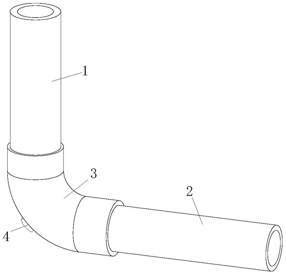
[0037]a building drainage structure, Figure 1-Figure 3 As shown, it includes a vertical pipe 1, a horizontal pipe 2 and a pipe joint 3; the vertical pipe 1 and the horizontal pipe 2 are connected through the pipe joint 3; it also includes:

[0038] The anti-blocking module 4, the anti-blocking module 4 includes a through hole 41 provided on the pipe joint 3, a No. 1 pipe 42 installed on the outer wall of the pipe joint 3 and communicated with the through hole 41, and a No. 1 pipe 42 threaded. Closing cover 43;

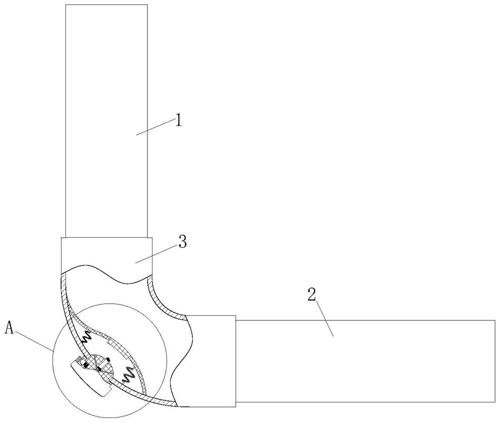
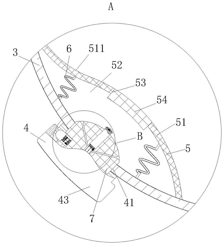
[0039] The buffer module 5, the buffer module 5 includes a buffer shrapnel 51 arranged on the inner wall of the pipe joint 3 and located at the corner of the pipe joint 3; a No. 1 area 52 is formed between the buffer shrapnel 51 and the inner wall of the pipe joint 3, and the buffer shrapnel 51 A No. 1 hole 53 is provided, and an elastic sealing plug 54 is threaded on the No. 1 hole 53;

[0040] The through hole 41 is on the same plane as the No. 1 hole 53, and the ...

Embodiment 2

[0046] The difference from Embodiment 1 is that, as Figure 2-3 As shown, a group of pagoda-shaped springs 6 are arranged in the No. 1 area 52; one end with a large diameter in each of the pagoda-shaped springs 6 is connected to the inner wall of the buffer shrapnel 51, and the small-diameter end is connected to the end of the pipe joint 3. on the inner wall;

[0047] By arranging a group of pagoda-shaped springs 6, it is possible to further improve the buffering effect of the buffering shrapnel 51 on water and excrement, and to improve the restoring force of the buffering shrapnel 51, so as to prevent the buffering shrapnel 51 from being unable to buffer water and excrement. Restore; In addition, the big end of pagoda-shaped spring 6 diameters is connected on the inwall of cushioning shrapnel 51, when pagoda-shaped spring 6 was compressed, increased the contact area with buffering shrapnel 51, further ensured that buffering shrapnel 51 is opposite to water and Buffering effe...

Embodiment 3

[0051] The difference from the second embodiment is that, if Figure 2-Figure 4 as well as Figure 7 As shown, the No. 1 tube 42 is provided with an elastic column 7; one end of the elastic column 7 is located in the No. 1 area 52, and the other end is located in the No. 1 tube 42 and above the inner end surface of the blocking cover 43;

[0052] A No. 1 groove 421 is provided on the inner wall of the No. 1 pipe 42; a No. 2 slot 71 equal in diameter to the No. 1 slot 421 is provided on the elastic column 7, and an elastic clamping post is connected to the No. 2 slot 71 by a spring. 72. Through the mutual cooperation between the elastic clamping column 72 and the No. 1 slot 421, the locking of the position of the elastic column 7 is realized;

[0053] The elastic column 7 is provided with the No. 3 slot 73 communicating with the No. 2 slot 71, and the No. 3 slot 73 is provided with a push rod 74; one end of the push rod 74 is connected with the elastic clamp post 72, and the o...


PUM


Abstract

The invention belongs to the technical field of buildings, and particularly relates to a building drainage structure which comprises a vertical pipe, a transverse pipe and a pipe joint. The vertical pipe and the transverse pipe are connected through the pipe joint; the system further comprises an anti-blocking module and a buffer module. By arranging the buffer module composed of the buffer elastic pieces and the anti-blocking module composed of the through hole, the first pipe and the blocking cover, the through hole is covered with the buffer elastic pieces, impact caused by water flow and excrement is relieved through the buffer elastic pieces, the situation that the impact directly acts on the inner wall of the pipe joint, and consequently the pipe joint is damaged is avoided, and meanwhile the anti-blocking effect is achieved. And the situation that the plugging cover is separated from the first pipe due to direct action on the plugging cover, water and excrement flow out of the through hole, and the indoor living environment is affected can be avoided, so that the service life of the pipe joint can be prolonged, the indoor living environment can be improved, and the drainage capacity of the building drainage structure is improved.

Description

technical field [0001] The invention belongs to the technical field of buildings, in particular to a building drainage structure. Background technique [0002] With the continuous improvement of residential requirements of Chinese residents, ensuring the safety of building drainage, avoiding water seal damage, and discharging sewage and wastewater outdoors smoothly and quickly has become the basic requirement of architectural design; the internal drainage system of buildings is divided into rainwater drainage system and sewage Wastewater drainage system, in order to quickly and safely discharge sewage to the outside, the basic components of the sewage drainage system in high-rise buildings include the following parts: water receivers for production equipment, sanitary appliances, cleaning equipment, ventilation pipes and drainage pipes; [0003] Among them, the drainage pipes of high-rise buildings have more specific requirements, including discharge pipes, main pipes, stand...

Claims


Application Information

Patent Timeline
Patent Type & Authority Applications(China)
IPC IPC(8): E03C1/12E03C1/122F16L55/24
CPCE03C1/12E03C1/122F16L55/24E03C2001/1206Y02A20/00
Inventor 王海将
Owner 江苏伟中景观建设有限公司
Why Eureka
Try Eureka