
Device and method for identifying internal force chain of three-dimensional particle system

A technology for identifying force and particles, which is applied in the analysis of materials, phase influence characteristic measurement, instruments, etc., can solve problems such as lack of research, and achieve the effect of simple device structure and low cost

Pending Publication Date: 2022-03-22
QINGDAO TECHNOLOGICAL UNIVERSITY
View PDF0 Cites 1 Cited by
  • Summary
  • Abstract
  • Description
  • Claims
  • Application Information

AI Technical Summary

Problems solved by technology

[0004] It can be seen that most of the current research on the force chain of the particle system is still at the two-dimensional level, and there is a lack of research on the third dimension, that is, the interior of the material.

Method used


Image

  • Device and method for identifying internal force chain of three-dimensional particle system
  • Device and method for identifying internal force chain of three-dimensional particle system
  • Device and method for identifying internal force chain of three-dimensional particle system

Examples


Embodiment 1

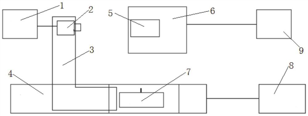
[0048] This embodiment provides a device for identifying internal force chains in a three-dimensional particle system.

[0049] A device for identifying force chains within a three-dimensional particle system, comprising:

[0050] The level 4 is used to place the experiment box 5; the laser 7 arranged on the level 4 is used to turn on the laser before the camera 2 shoots, so that the laser surface coincides with the inner wall of the experiment box 5;

[0051] The pressure testing machine 6 arranged on one side of the level meter 4 is used to apply successively increasing pressure or apply successively decreasing pressure to the particles in the test box 5;

[0052] A camera 2 connected to a spirit level, the camera 2 is used to take images of particles;

[0053] The level 4, laser 7, pressure testing machine 6 and camera 2 are all connected to the computer 1 or 9; the computer 1 or 9 is used to obtain the three-dimensional shape of the particle system according to the image ...

Embodiment 2

[0076] This example provides a method for identifying force chains within a three-dimensional particle system.

[0077] A method for identifying internal force chains in a three-dimensional particle system, using the method for identifying internal force chains in a three-dimensional particle system described in Embodiment 1, including:

[0078] Put the debugging granules into the experiment box, prepare the sucrose solution, and inject the sucrose solution into the experiment box;

[0079] Constantly change the concentration of the sucrose solution in the experimental box until the refractive index of the sucrose solution is the same as that of the debugging particles;

[0080] Take out the debugging granules and sucrose solution in the experiment box;

[0081] Put the experimental particles into the experimental box, and inject the sucrose solution and fluorescent material;

[0082] Place the experimental box with the experimental granules and sucrose solution on the test ...


PUM


Abstract

The invention provides a device and a method for identifying an internal force chain of a three-dimensional particle system. The device comprises a gradienter used for placing an experiment box; the laser is arranged on the gradienter and is used for turning on laser before the camera shoots, so that a laser surface is overlapped with the inner wall of the experiment box; the pressure testing machine is arranged on one side of the gradienter and is used for applying sequentially increased pressure or sequentially reduced pressure to the particles in the experiment box; the camera is connected with the gradienter and used for shooting images of the particles; the gradienter, the laser, the pressure testing machine and the camera are all connected with the computer; and the computer is used for obtaining the three-dimensional form of the particle system according to the image shot by the camera so as to identify the force chain.

Description

technical field [0001] The invention belongs to the microcosmic field, and in particular relates to a device and method for identifying internal force chains in a three-dimensional particle system. Background technique [0002] The statements in this section merely provide background information related to the present invention and do not necessarily constitute prior art. [0003] The propagation path of the force between particles (ie, the force chain) determines the macroscopic and microscopic mechanical properties of the particulate matter. In recent years, researchers have used various methods to study the forces on particles. Sanfratello studied the distribution of the force chain length in the two-dimensional photoelastic particle system, and obtained the law that the length of the force chain decays exponentially with the change of the applied force. Young-Hoon Jung uses photoelasticity measurement technology to visualize the force situation and force transmission p...

Claims


Application Information

Patent Timeline
Patent Type & Authority Applications(China)
IPC IPC(8): G01N15/00G01N21/41
CPCG01N15/00G01N21/41
Inventor 陈凡秀钟宜辰孙洁张兆军马庆元刘兆亮
Owner QINGDAO TECHNOLOGICAL UNIVERSITY
Learn More