

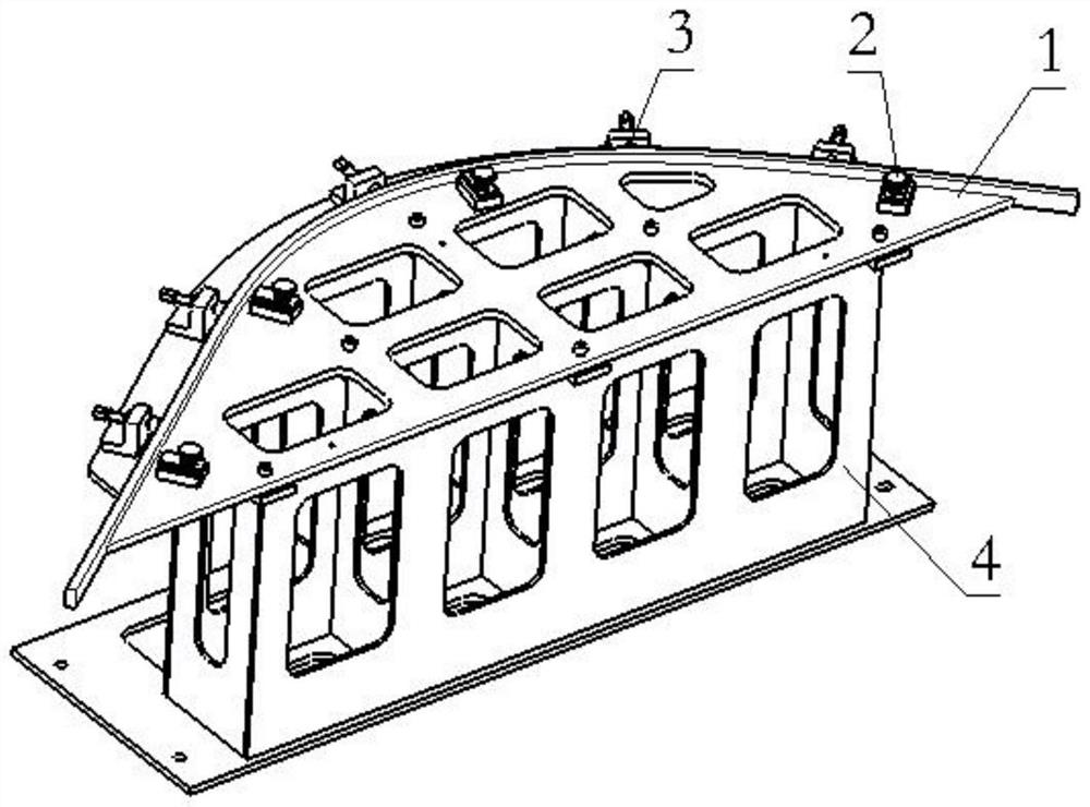
Three-dimensional laser trimming tool for L-shaped stretch-bending part
A three-dimensional laser and bending technology, applied in laser welding equipment, auxiliary devices, manufacturing tools, etc., can solve the gap in the modification effect of parts, which cannot meet the product accuracy requirements, the hardness of L-shaped stainless steel bending parts is large, and the size of the joint surface is not large. Matching and other issues to achieve the effect of reducing the difficulty of trimming, high precision and reliable installation
- Summary
- Abstract
- Description
- Claims
- Application Information
AI Technical Summary
Problems solved by technology
Method used
Image

Examples
Embodiment Construction
[0018] The technical solutions of the present invention will be clearly and completely described below in conjunction with the accompanying drawings. Apparently, the described embodiments are some of the embodiments of the present invention, but not all of them. Based on the embodiments of the present invention, all other embodiments obtained by persons of ordinary skill in the art without making creative efforts belong to the protection scope of the present invention.
[0019] In the description of the present invention, it should be noted that if the terms "center", "upper", "lower", "left", "right", "vertical", "horizontal", "inner", "outer" appear ", etc., the indicated orientation or positional relationship is based on the orientation or positional relationship shown in the drawings, which is only for the convenience of describing the present invention and simplifying the description, rather than indicating or implying that the referred device or element must have a specif...
PUM
 Abstract
Description
Claims
Application Information