Electric mechanical gripper with self-locking function and method for judging article clamping of electric mechanical gripper

A mechanical claw and functional technology, applied in the field of mechanical claw, can solve problems such as the inability to meet the positioning accuracy and high grasping accuracy, the rigid structure of the pneumatic mechanical claw, and the inability to stop and go immediately, so as to improve the use efficiency and service life. The effect of taking high precision and improving the service life

Pending Publication Date: 2022-03-25
ONCE TOP MOTOR MFG
View PDF0 Cites 0 Cited by
  • Summary
  • Abstract
  • Description
  • Claims
  • Application Information

AI Technical Summary

Problems solved by technology

[0003] Mechanical claws can be divided into pneumatic mechanical claws and electric mechanical claws according to the driving power source. The clamping force of pneumatic mechanical claws is stable and greater than that of electric mechanical claws, but similarly, pneumatic mechanical claws are rigid in structure and large in size. , high noise, difficult to control the speed, unable to stop and go, unable to meet the requirements of high positioning accuracy and grasping accuracy

Method used


Image

  • Electric mechanical gripper with self-locking function and method for judging article clamping of electric mechanical gripper
  • Electric mechanical gripper with self-locking function and method for judging article clamping of electric mechanical gripper
  • Electric mechanical gripper with self-locking function and method for judging article clamping of electric mechanical gripper

Examples


Embodiment Construction

[0039] In order to make the object, technical solution and advantages of the present invention clearer, the present invention will be further described in detail below in conjunction with the accompanying drawings and embodiments. It should be understood that the specific embodiments described here are only used to explain the present invention, not to limit the present invention. In addition, the technical features involved in the various embodiments of the present invention described below can be combined with each other as long as they do not constitute a conflict with each other.

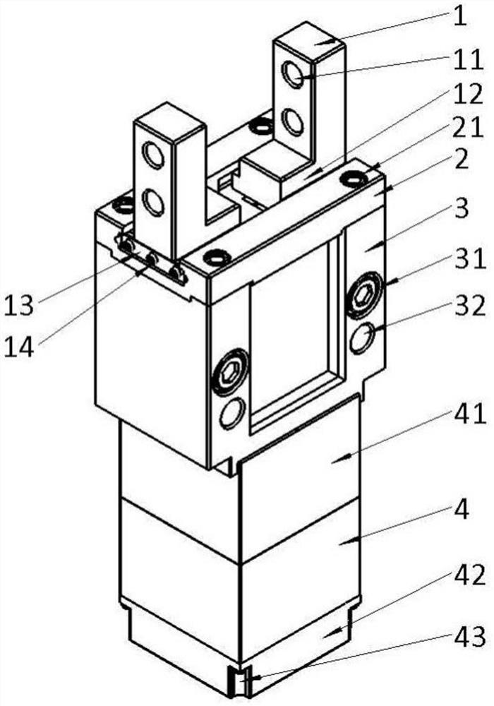
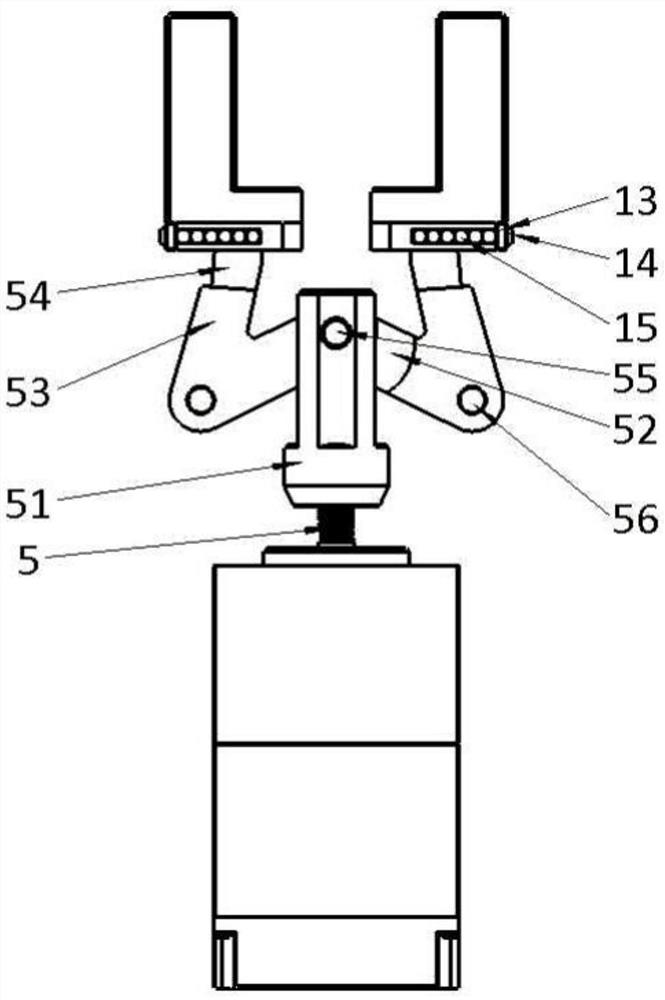
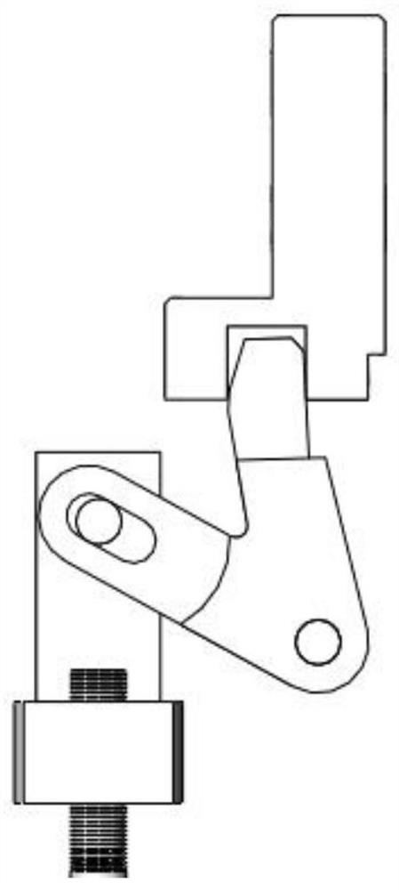
[0040] refer to Figure 1 ~ Figure 3 , an electromechanical claw with self-locking function, including a geared motor, a casing, a screw pair and two sets of jaw assemblies oppositely arranged, wherein:

[0041] The geared motor is installed on the casing, and the output shaft of the geared motor is set upward.

[0042] The lead screw pair includes a lead screw 5 and a lead screw nut 51 mounte...


PUM


Abstract

The invention discloses an electric mechanical gripper with a self-locking function. The electric mechanical gripper comprises a gear motor, a machine shell, a lead screw pair and two clamping jaw assemblies which are oppositely arranged. The lead screw pair comprises a lead screw and a lead screw nut, and a round pin shaft is arranged on the lead screw nut; the clamping jaw assembly comprises a clamping jaw, a sliding block and a V-shaped rod, the clamping jaw comprises the sliding block and clamping fingers, a containing groove is formed in the bottom of the sliding block, the V-shaped rod comprises a rod A and a rod B, the joint of the rod A and the rod B is hinged to the machine shell through a hinge shaft, the rod A extends into the containing groove and is provided with an inclined face, the rod B is provided with a guide groove, and a round pin shaft is slidably installed in the guide groove. The circular pin shaft is driven by the lead screw nut to move in the guide groove, so that the circular pin shaft drives the V-shaped rod to rotate around the center line of the hinge shaft, and the first end of the opening of the V-shaped rod pokes the sliding block. According to the invention, lead screw nut transmission is adopted, a self-locking function is realized, the gear motor can be prevented from entering a locking state, and the service life of the gear motor can be prolonged.

Description

technical field [0001] The invention belongs to the field of mechanical claws, and more specifically relates to an electric mechanical claw with a self-locking function and a method for judging a gripping object thereof. Background technique [0002] As we all know, robotic equipment has played an increasingly important role in helping people produce and live. With the development of science and technology, the use of robots in all walks of life has become more popular, and the mechanical arms and claws on robots are like human Hands, like hands, are an essential part of functioning. [0003] Mechanical claws can be divided into pneumatic mechanical claws and electric mechanical claws according to the driving power source. The clamping force of pneumatic mechanical claws is stable and greater than that of electric mechanical claws, but similarly, pneumatic mechanical claws are rigid in structure and large in size. , the noise is high, and it is difficult to control the spee...

Claims


Application Information

Patent Timeline
Patent Type & Authority Applications(China)
IPC IPC(8): B25J15/08
CPCB25J15/08
Inventor 翁孟坤张贝妮周志鹏
Owner ONCE TOP MOTOR MFG
Why Eureka
Try Eureka