Online intermittent 180-degree high-speed turnover device suitable for flat products
A turning device and intermittent technology, applied in the direction of transportation and packaging, conveyor objects, conveyors, etc., can solve the problems of missing or wrong turning, lack of physical strength, distraction, etc., to reduce the transmission speed and reduce work energy consumption , the effect of simple overall structure
- Summary
- Abstract
- Description
- Claims
- Application Information
AI Technical Summary
Problems solved by technology
Method used
Image

Examples
Embodiment Construction
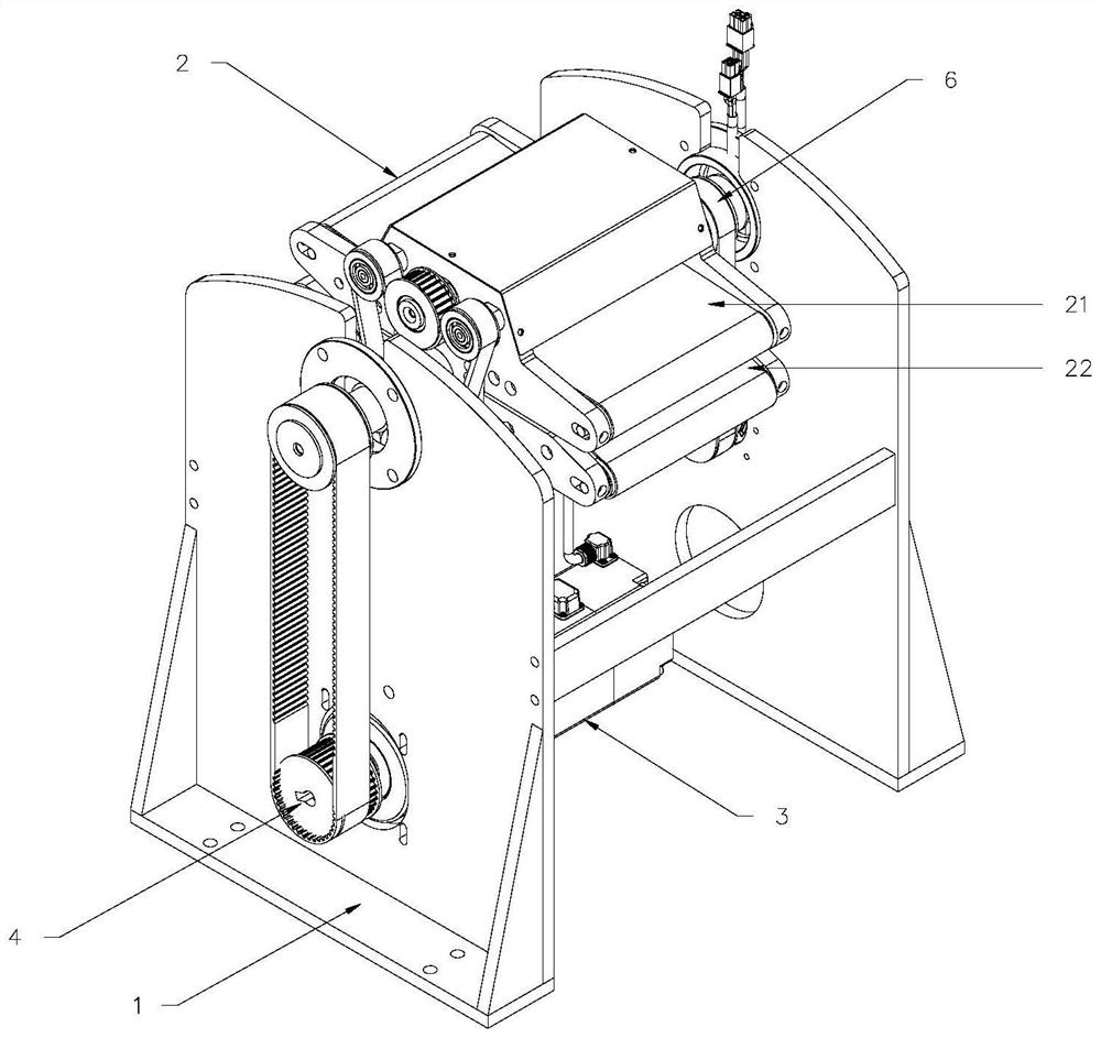
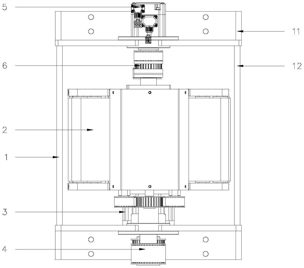
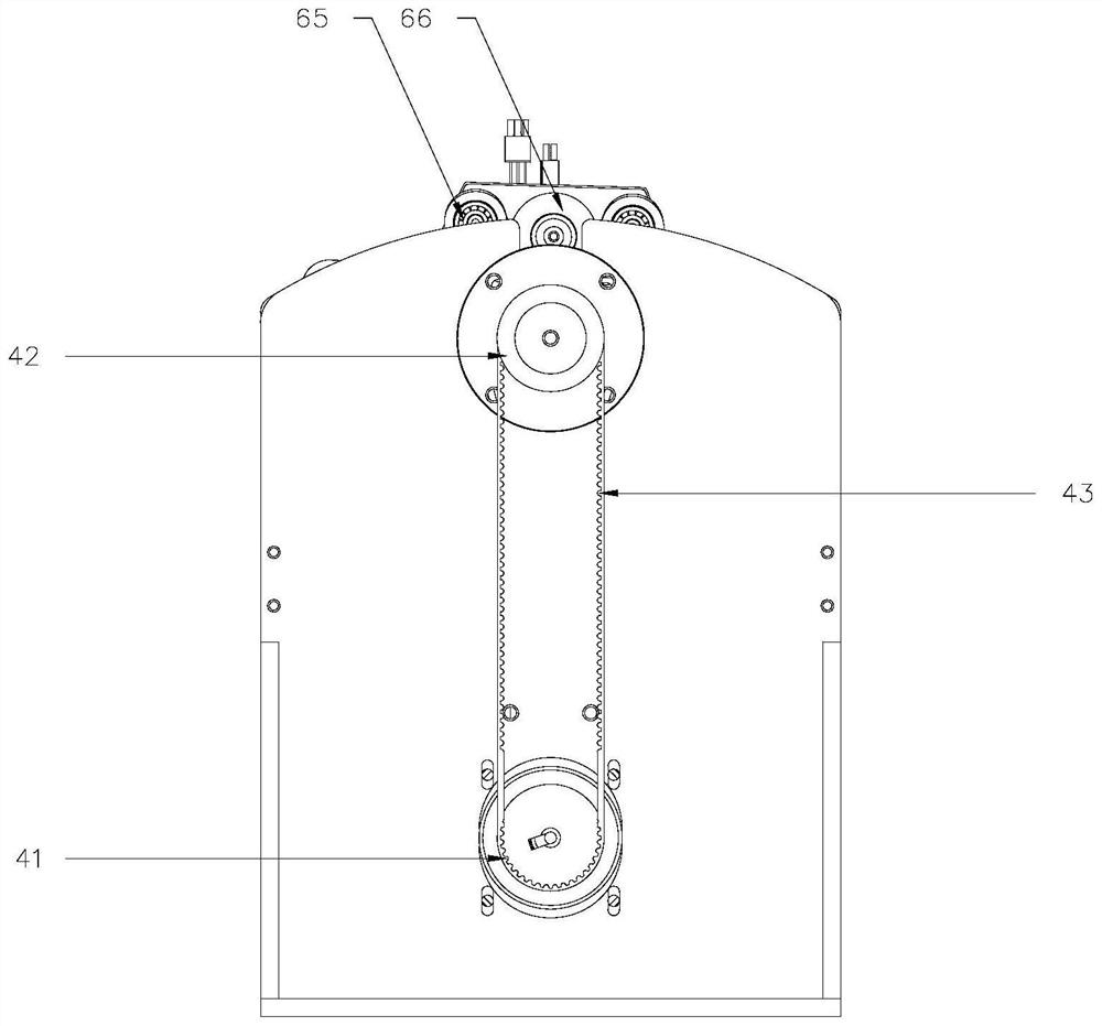
[0021] refer to Figure 1 to Figure 5 , the present invention is an online intermittent 180-degree high-speed turning device suitable for flat products, including a frame 1, a turning plate 2, a main motor 3, a main transmission assembly 4, an auxiliary motor 5, an auxiliary transmission assembly 6 and a controller. The turning disc 2 includes two conveyor belts 21 arranged in parallel and forming a gap 22 for flat products to pass through. The auxiliary motor 5 drives the belt bodies 214 of the two conveyor belts 21 to rotate in opposite directions through the auxiliary transmission assembly 6 at the same time so that The flat product moves along the conveying direction in the gap 22, and the main motor 3 simultaneously drives the two conveyor belts 21 on the frame 1 through the main transmission assembly 4 to rotate the axis perpendicular to the conveying direction in the middle of the gap 22 so that the flat product 180 ° flipping, the controller is electrically connected w...
PUM
 Abstract
Description
Claims
Application Information
PatSnap Eureka turns technology decisions into work you can execute. Powered by our Innovation Knowledge Graph, it runs expert workflows across engineering, life sciences, materials and intellectual property. Get your review-ready output in minutes.


