Coiled tubing peristaltic device for petroleum engineering

A technology of petroleum engineering and peristalsis, applied in the field of peristalsis, can solve problems such as time-consuming, energy consumption, low efficiency, slow operation, etc., to achieve the effect of improving drilling efficiency

Pending Publication Date: 2022-03-25
JIANGSU AERO SPACE HONGPENG NUMERICAL CONTROL MACHINERY
View PDF0 Cites 0 Cited by
  • Summary
  • Abstract
  • Description
  • Claims
  • Application Information

AI Technical Summary

Problems solved by technology

[0002] In the process of oil drilling, due to the complex underground geology, sometimes lateral drilling is required to avoid complex geological structures. At present, the traditional drill bit runs slowly in the lateral direction, which consumes a lot of time and energy, and is inefficient.

Method used


Image

  • Coiled tubing peristaltic device for petroleum engineering
  • Coiled tubing peristaltic device for petroleum engineering

Examples


Embodiment Construction

[0015] The present invention will be further explained below in conjunction with the accompanying drawings and specific embodiments. It should be understood that the following specific embodiments are only used to illustrate the present invention and are not intended to limit the scope of the present invention.

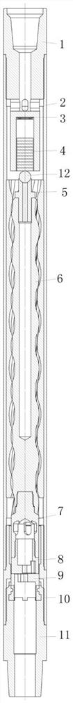
[0016] As shown in the figure, a coiled tubing peristaltic device for petroleum engineering includes an upper joint 1, a stator outer cylinder 2, an over-short connection 10 and a lower joint 11 connected sequentially from top to bottom. The stator outer cylinder 2 is a circular tubular structure. The lower end of the upper joint 1 extends into the upper end of the stator outer cylinder 2, and the outer side of the middle part is connected with the inner upper end of the stator outer cylinder 2. The middle part of the lower end of the upper joint 1 is provided with a mounting groove, and a disc spring arranged up and down is arranged in the mounting groove. 3 and slidi...


PUM


Abstract

The coiled tubing peristaltic device for petroleum engineering comprises an upper connector, a stator outer cylinder, a transition pup joint and a lower connector which are sequentially connected from top to bottom, the stator outer cylinder is of a circular-tube-shaped structure, the lower end of the upper connector extends into the upper end of the stator outer cylinder, and the outer side of the middle of the upper connector is connected with the inner side of the upper end of the stator outer cylinder in a matched mode; a mounting groove is formed in the middle of the lower end of the upper connector, a disc spring and a sliding gasket are vertically arranged in the mounting groove, a wriggling assembly is assembled in the stator outer cylinder, and a valve element assembly is assembled in the transition pup joint. When the pressure of liquid in the peristaltic device rises, the rotor starts to rotate and drives the upper valve element at the lower end to rotate, and the eccentric nozzle of the upper valve element and the eccentric nozzle of the lower valve element fixed below enable the flow area of the fluid channel to change, so that the pressure in the peristaltic device also changes, and the peristaltic device creeps. The wriggling in the transverse direction can be achieved, and the drilling efficiency is greatly improved.

Description

technical field [0001] The invention relates to the technical field of peristaltic devices, in particular to a coiled tubing peristaltic device for petroleum engineering. Background technique [0002] In the process of oil drilling, due to the complex underground geology, lateral drilling is sometimes required in order to avoid complex geological structures. At present, the traditional drill bit runs slowly in the lateral direction, which consumes a lot of time and energy, and is inefficient. Contents of the invention [0003] In order to solve the above problems, the invention discloses a coiled tubing peristaltic device for petroleum engineering. [0004] The specific plan is as follows: [0005] A coiled tubing peristaltic device for petroleum engineering, characterized in that: it includes an upper joint, a stator outer cylinder, an over-short connection and a lower joint sequentially connected from top to bottom, the stator outer cylinder is a circular tubular struct...

Claims


Application Information

Patent Timeline
Patent Type & Authority Applications(China)
IPC IPC(8): E21B7/06E21B12/00E21B41/00
CPCE21B7/061E21B12/00E21B41/00
Inventor 陈燕朱振今赵昱开姜领
Owner JIANGSU AERO SPACE HONGPENG NUMERICAL CONTROL MACHINERY
Why Eureka
Try Eureka