Eureka AIR delivers breakthrough ideas for toughest innovation challenges, trusted by R&D personnel around the world.

Backlight module and display device

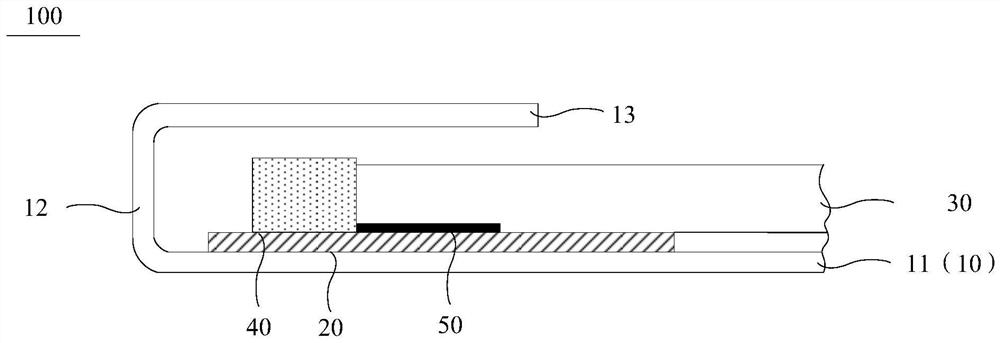
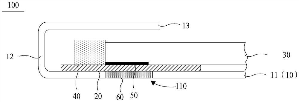
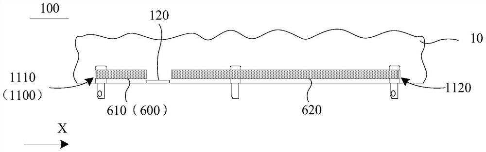
A backlight module and display panel technology, which is applied in identification devices, light guides, optics, etc., can solve problems such as uneven brightness and darkness on the light output side of the light source, pulling of the flexible circuit board, and changes in the gap between the light source and the light guide plate.

Pending Publication Date: 2022-03-25
WUHAN CHINA STAR OPTOELECTRONICS TECH CO LTD
View PDF4 Cites 0 Cited by
  • Summary
  • Abstract
  • Description
  • Claims
  • Application Information

AI Technical Summary

Problems solved by technology

[0003] At present, the backlight modules of narrow-frame notebook computers that are widely used in the market and have mass production experience usually use the upper part of the bottom frame to bend inward to form a U-shaped flip-chip structure with the side of the bottom frame. In the U-shaped structure, The light source is arranged on one side of the flexible circuit board, and the light guide plate is connected to the flexible circuit board through lamp glue, and is located on the light output path of the light source; however, due to the design of the U-shaped structure, there cannot be any gap between the light guide plate and the light source. Fixed connection, during the thermal shock test (quick switching cycle between high temperature environment and low temperature environment, to test the reliability of the product in extreme environments), due to the large expansion and contraction (expansion and contraction) of the light guide plate, it will affect the flexible circuit connected to it The board is pulled, causing the flexible circuit board to wrinkle, so that the light output angle of the light source connected to the flexible circuit board changes, which in turn causes the gap between the light source and the light guide plate to change, resulting in uneven brightness and darkness on the light output side of the light source

Method used


Image

  • Backlight module and display device
  • Backlight module and display device
  • Backlight module and display device

Examples


Embodiment Construction

[0033] The following will clearly and completely describe the technical solutions in the embodiments of the application with reference to the drawings in the embodiments of the application. Apparently, the described embodiments are only some of the embodiments of the application, not all of them. Based on the embodiments in this application, all other embodiments obtained by those skilled in the art without making creative efforts belong to the scope of protection of this application. In addition, it should be understood that the specific implementations described here are only used to illustrate and explain the present application, and are not intended to limit the present application. In this application, unless stated to the contrary, the used orientation words such as "up" and "down" usually refer to up and down in the actual use or working state of the device, specifically the direction of the drawing in the drawings ; while "inside" and "outside" refer to the outline of ...


PUM


Abstract

The invention provides a backlight module and a display device, and the backlight module comprises a frame body which comprises a first bottom plate; the flexible circuit board is arranged on the first bottom plate and located in the frame body; the light guide plate is arranged on the side, away from the first bottom plate, of the flexible circuit board and located in the frame body, and the orthographic projection of the light guide plate on the first bottom plate at least partially covers the orthographic projection of the flexible circuit board on the first bottom plate; the light source is arranged on the flexible circuit board and located on one side edge of the light guide plate; the lamp glue is arranged between the flexible circuit board and the light guide plate, and the flexible circuit board is connected with the light guide plate through the lamp glue; according to the backlight module, the through hole corresponding to the lamp glue is formed in the first bottom plate, the orthographic projection of the lamp glue in the direction perpendicular to the backlight module is located in the range of the through hole, and the fixing piece connected with the flexible circuit board is arranged in the through hole; the orthographic projection of the fixing piece in the direction perpendicular to the backlight module is at least partially overlapped with the orthographic projection of the lamp glue in the direction perpendicular to the backlight module.

Description

technical field [0001] The present application relates to the field of display technology, in particular to a backlight module and a display device. Background technique [0002] At present, notebook computer products are developing rapidly, and notebook computer products with narrow bezel and high screen-to-body ratio are favored by consumers due to their excellent product visual experience. Manufacturers and technical practitioners are also developing narrow bezel notebook computer products simultaneously. [0003] At present, the backlight modules of narrow-frame notebook computers that are widely used in the market and have mass production experience usually use the upper part of the bottom frame to bend inward to form a U-shaped flip-chip structure with the side of the bottom frame. In the U-shaped structure, The light source is arranged on one side of the flexible circuit board, and the light guide plate is connected to the flexible circuit board through lamp glue, and...

Claims


Application Information

Patent Timeline
Patent Type & Authority Applications(China)
IPC IPC(8): G02B6/00G09F9/00
CPCG02B6/0086G02B6/0083G02B6/0088G02B6/009G09F9/00
Inventor 胡天赐
Owner WUHAN CHINA STAR OPTOELECTRONICS TECH CO LTD
Why Eureka
Eureka Blog
Learn More