Computer room wire fixing device

A technology for computer room and line fixing device, applied in the field of communication, can solve the problems of chaotic bundle of optical fiber lines, damage of optical fiber lines, fire hazard, etc., and achieve the effect of convenient fixed position, convenient fixed limit, and reasonable design.

Pending Publication Date: 2022-03-25
CHANGCHUN VOCATIONAL INST OF TECH
View PDF0 Cites 0 Cited by
  • Summary
  • Abstract
  • Description
  • Claims
  • Application Information

AI Technical Summary

Problems solved by technology

[0002] The computer room is a room where computers and other communication equipment are placed, and a large number of optical fiber cables are connected to it. In order to organize loose optical fiber cables, the common method is to bundle the optical fiber cables with cable ties, and then use cable ties to bind the optical fiber cables. On the rack on the wall of the equipment room, the cables are routed following the rack. However, in the actual work process, due to the chaotic bundling of multiple optical fiber cables by cable ties, the fixing of the optical fiber cables is not neat enough, so it is found that there are After the fiber optic cable is damaged, it is not easy for the staff to find and replace the damaged fiber optic cable, and because the fiber optic cable is in the long-term working process, and multiple optical fiber cables are fixed together, there is a certain fire hazard

Method used


Image

  • Computer room wire fixing device
  • Computer room wire fixing device
  • Computer room wire fixing device

Examples


Embodiment Construction

[0024] In order to enable those skilled in the art to better understand the present invention, the technical solution of the present invention will be further described below in conjunction with the accompanying drawings and embodiments.

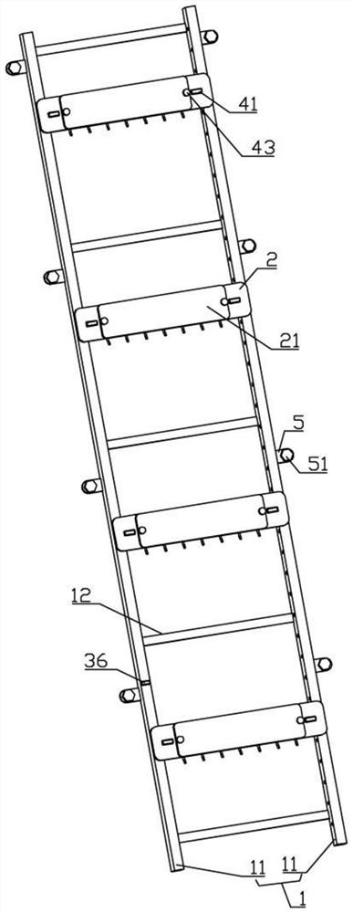
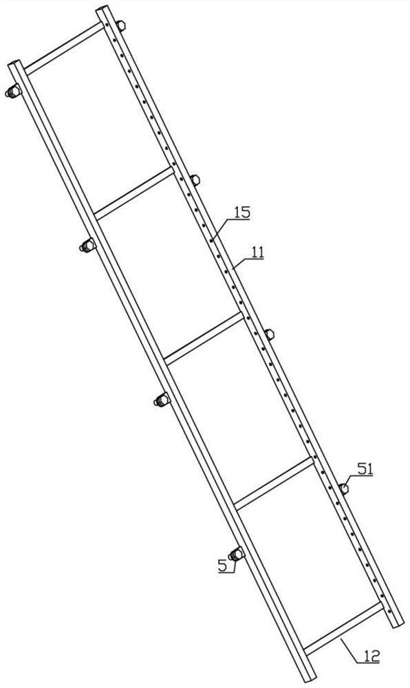
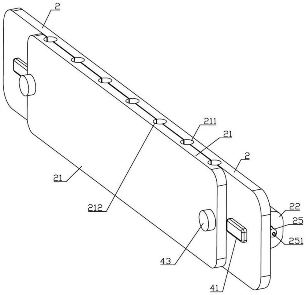
[0025] Such as Figure 1-7 As shown, a computer room fixing device of the present invention includes a frame 1, and the frame 1 is composed of two vertical rods 11, a connecting rod 12 is arranged between the two vertical rods 11, and the vertical rod 11 on the right side An inner cavity 13 is provided, and the inner wall of one side of the inner cavity 13 is provided with a contact plate 14, and the opposite sides of the two vertical bars 11 are provided with several lock holes 15, and some lock holes 15 on the right side communicate with the inner cavity 13, two The vertical bar 11 is equipped with a number of fixing mechanisms, the fixing mechanism includes a mounting plate 2 and a pressure plate 21, the mounting plate 2 is provided with ...


PUM


Abstract

The invention belongs to the technical field of communication, and particularly relates to a computer room wire fixing device which comprises a rack, a power connection piece is arranged on the inner wall of one side of an inner cavity, a plurality of lock holes are formed in the opposite sides of two vertical rods, the two vertical rods are provided with a plurality of fixing mechanisms, and stepped holes are formed in the sides, away from each other, of two fixing blocks. The two springs are provided with T-shaped locking pieces extending out of the stepped holes, the end face of the T-shaped locking piece on the right side is provided with a power connection block matched with the power connection piece, the left side and the right side of the mounting plate are provided with pulling assemblies matched with the T-shaped locking pieces, and a plurality of spraying heads are assembled on the lower side of the distribution pipe. According to the invention, a worker can conveniently fix and limit the optical fiber cable in the later period, the worker can conveniently adjust the fixing position of the optical fiber cable, the overall design is convenient for supplying power to the fire detectors of the plurality of mounting plates, the fire can be detected in real time, and when the fire occurs, the fire extinguishing work can be automatically carried out.

Description

technical field [0001] The invention belongs to the technical field of communication, and in particular relates to a line fixing device for a computer room. Background technique [0002] The computer room is a room where computers and other communication equipment are placed, and a large number of optical fiber cables are connected to it. In order to organize loose optical fiber cables, the common method is to bundle the optical fiber cables with cable ties, and then use cable ties to bind the optical fiber cables. On the rack on the wall of the equipment room, the cables are routed following the rack. However, in the actual work process, due to the chaotic bundling of multiple optical fiber cables by cable ties, the fixing of the optical fiber cables is not neat enough, so it is found that there are After the optical fiber cable is damaged, it is not easy for the staff to find and replace the damaged optical fiber cable, and because the optical fiber cable is in the long-te...

Claims


Application Information

Patent Timeline
IPC IPC(8): G02B6/44A62C3/16A62C37/00
CPCG02B6/4452A62C3/16A62C37/00
Inventor 张立辉李京泽
Owner CHANGCHUN VOCATIONAL INST OF TECH
Why Eureka
Try Eureka