Battery cell assembly, battery module and battery system
A battery module and battery system technology, applied to battery components, electrical components, circuits, etc., can solve the problems of low battery module utilization and volume utilization
- Summary
- Abstract
- Description
- Claims
- Application Information
AI Technical Summary
Problems solved by technology
Method used
Image

Examples
Embodiment 1
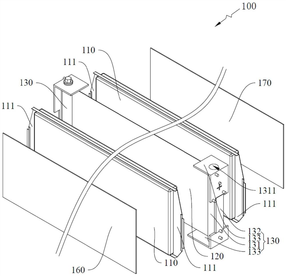
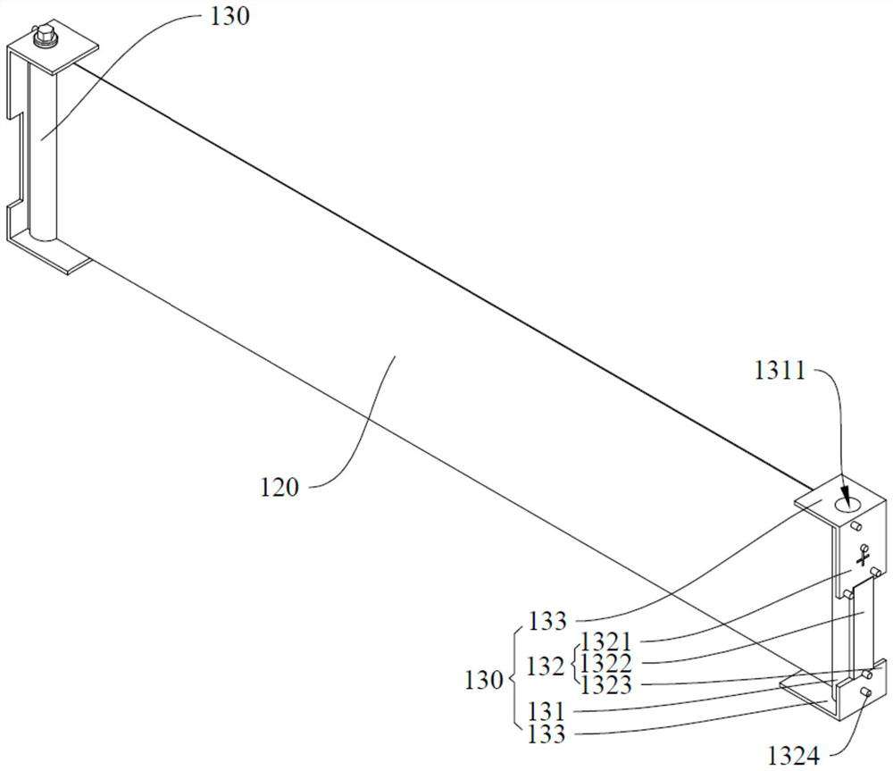
[0067] see figure 1 , figure 2 , the embodiment of the present invention provides a cell assembly 100 , including two cell units 110 , two cell units 110 and at least one insulating support 130 . Among them, the two cell units 110 are arranged in an array along its thickness direction, and the two ends of the cell unit 110 in the length direction are connected with sealing edges 111; the support plate 120 is arranged between the two cell units 110, and is connected The unit 110 is fixedly connected; the insulating bracket 130 includes a main body 131 fixedly connected to the end of the support plate 120 and arranged between the sealing edges 111 of the two cell units 110, the main body 131 is provided with a fixing hole 1311, and the extension direction of the fixing hole 1311 perpendicular to the length direction of the cell unit 110 .
[0068] It should be noted here that, in the cell assembly 100 provided in this embodiment, the opposite sides of the two cell units 110 a...
Embodiment 2
[0120] The difference between this embodiment and Embodiment 1 is:
[0121] see Figure 9 , Figure 10 , in this embodiment, the cell assembly 100 further includes an electrical connector 140 fixedly connected to the side of the vertical plate 132 away from the support plate 120 , and an electrical connector 140 arranged on the horizontal plate 133 and vertically connected to one end of the electrical connector 140 The confluence part 150 is provided with a confluence hole 151 which is arranged through and aligned with the fixing hole 1311 .
[0122] It should be noted here that, in this embodiment, after one end of the two cell units 110 of the cell assembly 100 is fixed to the support plate 120, the lugs at the ends can be welded to the electrical connector 140 first. , so as to realize the power connection of the two battery cells 110 at the end. Subsequently, the electricity of the two battery cells 110 can be conducted to the bus 150 integrally connected with the elect...
PUM
 Abstract
Description
Claims
Application Information
 - R&D
- Intellectual Property
- Life Sciences
- Materials
- Tech Scout
- Unparalleled Data Quality
- Higher Quality Content
- 60% Fewer Hallucinations
Browse by: Latest US Patents, China's latest patents, Technical Efficacy Thesaurus, Application Domain, Technology Topic, Popular Technical Reports.
© 2025 PatSnap. All rights reserved.Legal|Privacy policy|Modern Slavery Act Transparency Statement|Sitemap|About US| Contact US: help@patsnap.com