
Control system for stabilizing floating wind turbine

A technology for wind turbines, control systems, applied in the configuration of installing/supporting wind turbines, equipment to increase the stability of ships, floating buildings, etc., can solve the detuned stability and control performance, poor rotational speed tracking ability, etc. question

Pending Publication Date: 2022-03-25
SIEMENS GAMESA RENEWABLE ENERGY AS
View PDF0 Cites 0 Cited by
  • Summary
  • Abstract
  • Description
  • Claims
  • Application Information

AI Technical Summary

Problems solved by technology

However, this comes with poor rotational velocity tracking
Detuning can be a compromise between stability and control performance

Method used


Image

  • Control system for stabilizing floating wind turbine
  • Control system for stabilizing floating wind turbine
  • Control system for stabilizing floating wind turbine

Examples


Embodiment Construction

[0103] The illustrations in the figures are schematic. It is to be noted that in different figures, similar or identical elements or features are provided with the same reference signs or with reference signs which differ from the corresponding reference signs only within the first digit. In order to avoid unnecessary repetition, elements or features which have already been explained with respect to the previously described embodiments will not be explained again at a later point in the specification.

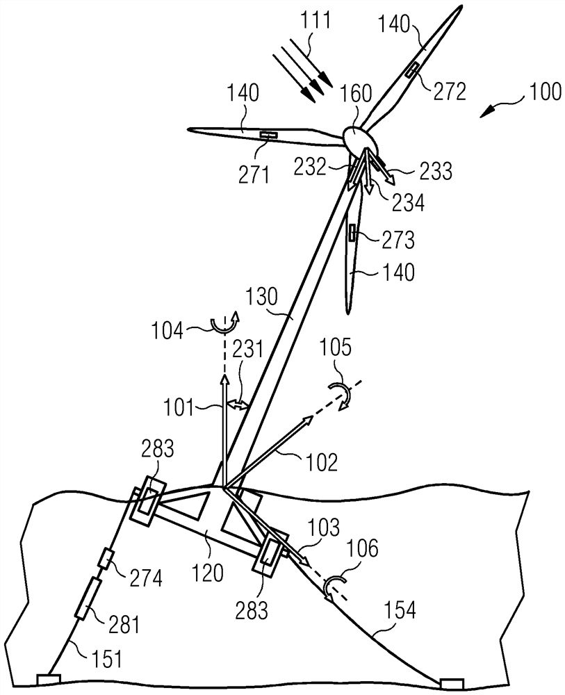
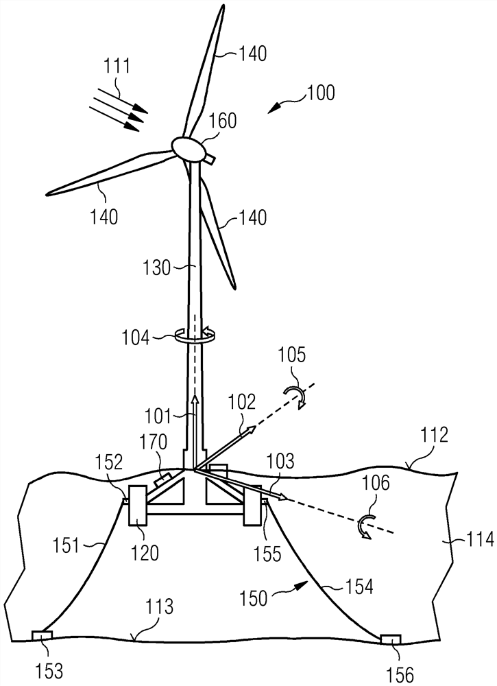
[0104] figure 1 A floating wind turbine 100 according to an exemplary embodiment of the present invention is shown in a predetermined equilibrium state. The floating wind turbine 100 includes three blades 140 mounted to a nacelle 160 , a tower 130 and a floating foundation 120 . The floating wind turbine 100 also includes a fixed structure 150 including a plurality of mooring cables. For clarity, figure 1 Only the first mooring line 151 and the second mooring line 154 are s...


PUM


Abstract

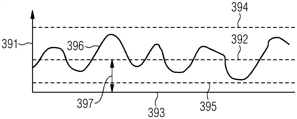
There is described a control system (170) for stabilizing a floating wind turbine (100), the control system (170) comprising: detection means (271, 272, 273, 274) configured for monitoring an offset (231) from a predetermined floating body pitch angle (393) of the floating wind turbine (100) and / or an offset from a predetermined floating body yaw angle of the floating wind turbine (100), the detection device (271, 272, 273, 274) is further configured for monitoring an oscillating movement (396) of a floating body pitch angle (392) and / or an oscillating movement of a floating body yaw angle, where the predetermined floating body pitch angle (393) and the predetermined floating body yaw angle define a predetermined equilibrium state of the floating wind turbine (100), where the predetermined equilibrium state of the floating wind turbine (100) is determined by the detection device (271, 272, 273, 274). The threshold value (394, 395) of the oscillating motion (396) of the floating body pitch angle (392) and the threshold value of the oscillating motion of the floating body yaw angle further define the predetermined equilibrium state of the floating wind turbine (100); and an actuating device (281, 282) which is designed to actuate the floating body pitch angle (392) and / or the floating body yaw angle until the predetermined equilibrium state is fulfilled, the actuating device (281, 282) being further designed to actuate the oscillating movement (396) of the floating body pitch angle (392) and / or the oscillating movement of the floating body yaw angle until the predetermined equilibrium state is fulfilled, the actuating device (281, 282) being designed to actuate the oscillating movement (396) of the floating body pitch angle (392) and / or the oscillating movement of the floating body yaw angle (392) until the predetermined equilibrium state is fulfilled. Until the predetermined equilibrium state of the floating wind turbine (100) is satisfied. Furthermore, a floating wind turbine (100) is described. In addition, a method for stabilizing a floating wind turbine (100) is described.

Description

technical field [0001] The invention relates to a control system for stabilizing a floating wind turbine. Furthermore, the invention relates to a floating wind turbine and a method for stabilizing a floating wind turbine. Background technique [0002] In the technical field of floating wind turbines, it is known that floating wind turbines may be subject to additional movements due to the additional degrees of freedom compared to conventional wind turbines. This additional movement can cause severe loads on the floating wind turbine and a drop in annual electricity production. For example, if the floating body pitches, the shear forces at the interface between the tower and the nacelle may increase due to the increased gravity load. Furthermore, for the rod-type buoy floating body concept of floating wind turbines, the conventional closed-loop speed-pitch control of the drive train may lead to instability of the floating body's pitch motion. This may be due to the disturb...

Claims


Application Information

Patent Timeline
IPC IPC(8): B63B35/44B63B39/00B63B21/50F03D13/25
CPCB63B35/44B63B39/00B63B21/50F03D13/25B63B2035/446Y02E10/727Y02E10/72F05B2240/93
Inventor T·埃斯本森K·劳格森
Owner SIEMENS GAMESA RENEWABLE ENERGY AS
Learn More