A medical sewage treatment device based on centrifugal separation of floating objects
A sewage treatment device and technology for floating objects, which are applied in separation methods, filtration separation, chemical instruments and methods, etc., can solve the problems of easy formation of vortices, difficulty in cleaning, and simultaneous throwing out, so as to eliminate the interference of vortices and improve filtration efficiency. , the effect of improving quality
- Summary
- Abstract
- Description
- Claims
- Application Information
AI Technical Summary
Problems solved by technology
Method used
Image
Examples
Embodiment 1
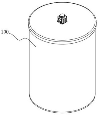
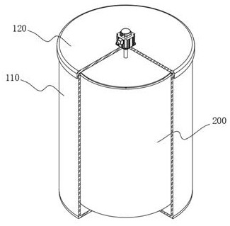
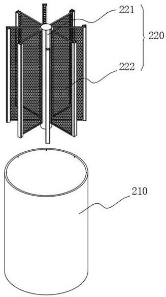
[0043] see figure 1 and figure 2 As shown, the purpose of this embodiment is to provide a medical sewage treatment device based on centrifugal separation of floating objects, including an external mechanism 100 and an internal mechanism 200, the external mechanism 100 includes an outer casing 110, and the internal mechanism 200 is arranged on the outer casing 110 inside, and rotate inside it to generate centrifugal force, see image 3 As shown, the internal mechanism 200 includes an inner housing 210 and a separation assembly 220, and the separation assembly 220 is disposed in the inner housing 210, wherein:
[0044] The tops of the outer shell 110 and the inner shell 210 are both open, the main purpose of which is to facilitate the injection of sewage into the inner shell 210;
[0045] The separation assembly 220 includes an inner column 221, which runs through the top wall of the inner housing 210 and is fixedly connected to the center of the bottom wall of the outer hous...
Embodiment 2
[0051] Considering the effect of centrifugal force, if the way of separating from the outside is adopted, the floating object may break through the separated filter screen 2233 under the action of centrifugal force. For this, please refer to Figure 5 As shown, the collector 223 includes a right-angle plate 2231 and an isolation block 2232, the isolation block 2232 is arranged in the opening of the right-angle plate 2231, and side plates 2234 are arranged on both sides of the right-angle plate 2231, wherein:
[0052] An inlet chamber 223D and a collection chamber 223C are formed between the isolation block 2232 and the right-angle plate 2231. The inlet chamber 223D is located on the top of the isolation block 2232, the collection chamber 223C is located on one side of the isolation block 2232, and the bottom of the collection chamber 223C is provided with a filter screen 2233.
[0053] working principle:
[0054] The right-angle plate 2231 in this embodiment makes the outer si...
Embodiment 3
[0059] In order to scrape the floating matter on the inner wall of the inner housing 210, please refer to Figure 7 As shown, the collecting piece 223 is provided with an outer cover 224, and the outer cover 224 is a "U"-shaped structure. The outer surface is made of rubber structure, which can scrape the floating objects attached to the inner wall of the inner housing 210 after being bonded to the inner wall of the inner housing 210 .
[0060] In addition, a circulation cavity 2241 is opened in the outer cover 224 near the sinking surface 223A, and its main purpose is to provide a drainage channel for the sewage flowing out of the sinking surface 223A.
PUM
 Abstract
Description
Claims
Application Information
 - R&D
- Intellectual Property
- Life Sciences
- Materials
- Tech Scout
- Unparalleled Data Quality
- Higher Quality Content
- 60% Fewer Hallucinations
Browse by: Latest US Patents, China's latest patents, Technical Efficacy Thesaurus, Application Domain, Technology Topic, Popular Technical Reports.
© 2025 PatSnap. All rights reserved.Legal|Privacy policy|Modern Slavery Act Transparency Statement|Sitemap|About US| Contact US: help@patsnap.com


