Port deburring device for rail transit vehicle brake pipe joint production

A rail transit vehicle and deburring technology, which is applied in the field of port deburring devices, can solve problems such as low work efficiency, high labor intensity, and inconvenient clamping, so as to reduce manual labor intensity, realize end face deburring, and improve processing efficiency Effect

Active Publication Date: 2022-03-29
JIAXING MASTER PLUMBING
View PDF10 Cites 0 Cited by
  • Summary
  • Abstract
  • Description
  • Claims
  • Application Information

AI Technical Summary

Problems solved by technology

[0002] In the production process of rail vehicle brake pipe joints, one of the first steps is to cut off the ends of the pipe joints to obtain the required finished joints. However, the section of the pipe joints after cutting is uneven because of the The burrs will also stick to the outer diameter edge and inner diameter edge of the pipe joint section, which is not only unsightly, but will also stab the user during later installation and use. For this reason, it will be deburred before sale; and The traditional deburring method is to chamfer the inner diameter and outer diameter edge of the pipe joint section. This method can not only effectively remove the burr but also make the processed pipe joint section more beautiful; but because the pipe joint is small, Not only is it inconvenient to clamp, but also requires repeated clamping and positioning, which is labor-intensive and low-efficiency;

Method used


Image

  • Port deburring device for rail transit vehicle brake pipe joint production
  • Port deburring device for rail transit vehicle brake pipe joint production
  • Port deburring device for rail transit vehicle brake pipe joint production

Examples


Embodiment 1

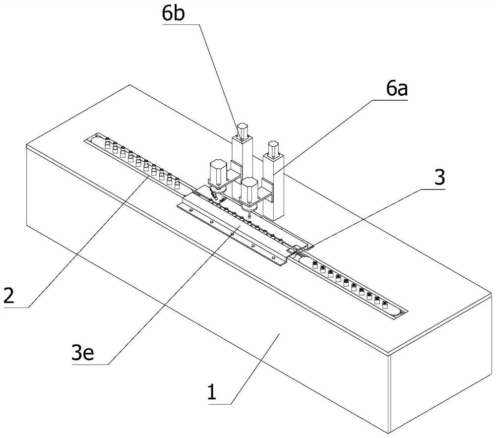
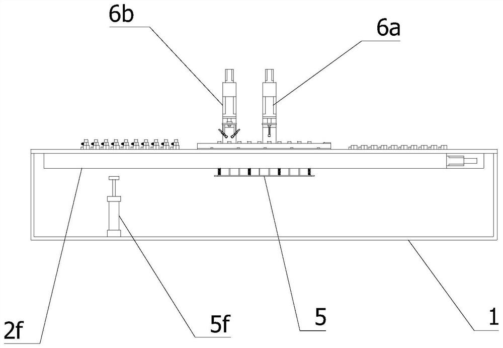
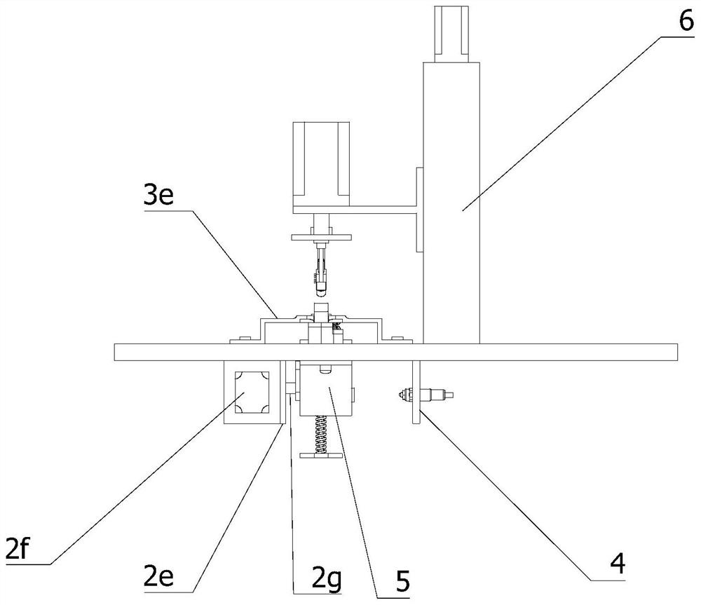
[0038] like Figure 1 to Figure 9 As shown, this application provides:

[0039]A port deburring device for the production of brake pipe joints of rail transit vehicles, comprising a frame 1, a linear reciprocating drive assembly 2, a material loading module 3, a sensing module 4, a material return assembly 5 and a deburring device 6; The reciprocating drive assembly 2 is horizontally embedded and installed on the upper surface of the frame 1 along the longitudinal direction of the frame 1; the loading module 3 is detachably arranged at the output end of the linear reciprocating drive assembly 2; at the bottom of the frame 1; the sensing module 4 is arranged in the middle of the linear reciprocating drive assembly 2; the material withdrawal assembly 5 is fixedly installed directly below the transmission end of the linear reciprocating drive assembly 2; the deburring device 6 is vertically arranged on the machine. The deburring device 6 is located on one side of the middle of t...

Embodiment 2

[0066] like Figure 7As shown, the second chamfering module 6b includes a third screw slide 6b1, a fifth connecting frame 6b2, a second servo motor 6b3, a second tool holder 6b4, an extension rod 6b5, a locking bolt 6b6 and a second chamfering knife 6b7; the fifth connecting frame 6b2 is fixedly installed on the output end of the third screw slide table 6b1; the second servo motor 6b3 is vertically arranged at the end of the fifth connecting frame 6b2; the output shaft of the second servo motor 6b3 passes through The second tool rest 6b4 is fixedly installed on the end of the output shaft of the second servo motor 6b3; the second tool rest 6b4 is coaxially arranged with the second servo motor 6b3 There are two extension rods 6b5, and the two extension rods 6b5 are in a mirror image state on both sides of the bottom of the second tool rest 6b4; the lower end of each extension rod 6b5 is also provided with an inclined slot; the second chamfering knife 6b7 can be The second cham...


PUM


Abstract

The invention relates to the technical field of pipe joint production, in particular to a port deburring device for rail transit vehicle brake pipe joint production, which comprises a rack, a linear reciprocating driving assembly, a material loading module, a sensing module, a material returning assembly and a deburring device, the linear reciprocating driving assembly is horizontally installed on the upper surface of the rack in an embedded mode in the long edge direction of the rack. The material carrying module is detachably arranged at the output end of the linear reciprocating driving assembly. The sensing module is arranged at the bottom of the rack; the material returning assembly is fixedly installed under the conveying end of the linear reciprocating driving assembly. The deburring device is vertically arranged on the rack; according to the pipe joint chamfering device, a plurality of pipe joints can be clamped at a time, the pipe joints are automatically limited and fixed in the clamping process, then the pipe joints are automatically conveyed, chamfered and returned, operation is easy, and the machining efficiency is high.

Description

technical field [0001] The invention relates to the technical field of pipe joint production, in particular to a port deburring device for the production of rail transit vehicle brake pipe joints. Background technique [0002] In the production process of rail transit vehicle brake pipe joints, one of the steps is to cut off the ends of the pipe joints to obtain the required finished joints, but the sections of the pipe joints after cutting are uneven, because the cutting The burr will also stick to the outer diameter edge and inner diameter edge of the pipe joint section, which is not only unsightly, but also stabs the user during the later installation, so it will be deburred before it is sold. The traditional deburring method is to chamfer the inner and outer diameter edges of the pipe joint section respectively. This method can not only effectively remove the burr but also make the processed pipe joint section more beautiful; however, due to the small size of the pipe jo...

Claims


Application Information

Patent Timeline
Patent Type & Authority Applications(China)
IPC IPC(8): B23D79/00
CPCB23D79/00
Inventor 沈辉陶凯洪哲周中皓
Owner JIAXING MASTER PLUMBING
Why Eureka
Try Eureka